Network Showcase
The Network Showcase enables users to focus on multiple areas of interest within their network, without disturbing the underlying hierarchical structure. The Network Showcase is especially helpful when you want to visualize a selected portion of the network in a separate space, without consideration of subnets or geographical layouts.
This section includes the following topics:
- Overview of the Network Showcase – describes the concepts and capabilities of the Network Showcase.
- Network Showcase Example Workflow and Example Workflow Steps: Using Network Showcase – describe a typical Network Showcase workflow and the associated procedures.
- Network Showcase Procedures – describes procedures, grouped by workflow categories.
- Network Showcase Pop-Up Menu – describes the pop-up menu options.
Overview of the Network Showcase
Each scenario can include multiple showcases. There is no limit to the number of showcases that can be defined for a scenario.
Additionally, each scenario includes a "Default" showcase. Note the following characteristics of the Default showcase:
- The Default showcase cannot be renamed or displayed in a floating window without first copying the showcase. For more information, see Copying a Showcase.
- The Default showcase cannot be deleted. To remove objects from the Default showcase, see Removing Featured Objects from a Showcase.
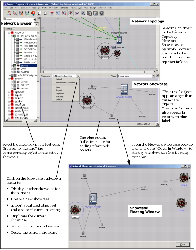
Network objects are added to a showcase by selecting the objects in either the Network Topology or Network Browser. Figure 49 shows a typical Network Showcase interface and how it relates to the Network Topology and Network Browser.
Figure 49: Network Showcase: User Interface and Relation to Network Topology/Network Browser
Showcases display two types of network objects:
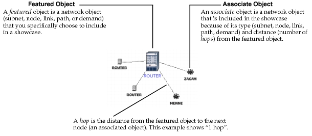
- Featured Objects – Network objects (node, link, path, demand, subnet) that you specifically choose to include in a showcase. Featured nodes are displayed as large color icons with blue labels. Featured links, paths, and demands are displayed with the same color, thickness, and line style as in the Network Topology.
- Associate Objects – Network objects are included in a showcase because of their type (node, link, path, demand, subnet) and distance (number of hops) from the featured object. Associate nodes are displayed as small gray-scale icons with small black labels. Associate links, paths, and demands are displayed with thin, dotted, black lines.
Figure 50: Concepts of the Showcase
Featured objects appear in the showcase using automatic layout. You can reposition objects within the showcase. However, object positions are not maintained from one session to another.
Since the showcase provides a view of selected objects, you cannot scroll through or zoom in/out of the showcase pane. However, you can resize the display of the showcase by sliding the divider bar between the Network Showcase and the Network Topology.
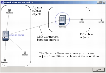
After configuring and adding featured objects to a showcase, you can display the showcase in a floating window. Figure 51 shows an example showcase in a floating window. In the example, the showcase displays objects from two subnets (Atlanta and DC) and shows how the objects in the subnets are connected. In the Network Topology, generally you cannot view objects from different subnets at the same time. However, in a showcase, you can simultaneously view objects from different subnets. Additionally, if the objects are connected in any way, the connection is shown in the showcase.
Figure 51: Example of a Showcase in a Floating Window
For more information, see:
- Network Showcase Example Workflow
- Example Workflow Steps: Using Network Showcase
- Network Showcase Procedures
- Network Showcase Pop-Up Menu
- Show Network Browser
Network Showcase Example Workflow
After defining a hierarchical network topology (either manually or imported from another source), you can simultaneously view specific network objects from different subnets.
Use the Network Showcase to
- show the path between two network devices
- display similar network devices (e.g., all ATM routers or HP servers)
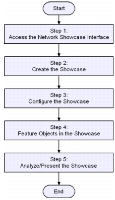
The following figure shows the typical workflow for showing the path between two network devices.
Figure 52: Network Showcase Workflow—Path Between Two Network Devices
For a description of the workflow steps, see Example Workflow Steps: Using Network Showcase.
Example Workflow Steps: Using Network Showcase
Use the following workflow steps to show the path between two network devices using the Network Showcase.
- Workflow Example Step 1: Access the Network Showcase Interface
- Workflow Example Step 2: Create the Showcase
- Workflow Example Step 3: Configure the Showcase
- Workflow Example Step 4: Feature Objects in the Showcase
- Workflow Example Step 5: Analyze/Present the Showcase
For an overview discussion of the Network Showcase, see Overview of the Network Showcase.
Workflow Example Step 1: Access the Network Showcase Interface
After defining the network topology, you can access the Network Showcase Interface.
Procedure 62: Workflow Example: Accessing the Network Showcase Interface
-
Choose View > Show Network Showcase.
For more information, see Accessing the Network Showcase Interface.
Workflow Example Step 2: Create the Showcase
Create a showcase for displaying "featured" objects.
Procedure 63: Workflow Example: Creating a Showcase
-
From the Showcase pull-down menu, select New…
Result: The Enter Name dialog box appears.
-
Enter the name for the new showcase and click OK.
Result: The new showcase appears in the Network Showcase pane.
For additional information, see Creating a Showcase.
Workflow Example Step 3: Configure the Showcase
Configuring the showcase allows you to customize characteristics and behavior of the showcase. For this example, the Network Showcase will be configured as follows:
- network object types to feature – Specifies the network objects that can be "featured" (added) in the showcase.
- network object types to associate with featured objects – Specifies the network object type(s) that can be included in a showcase as objects associated with featured objects.
- background color – Defines the background color for the showcase.
Procedure 64: Workflow Example: Configuring a Showcase
-
Define network object types to feature – By default, nodes, links, paths, and demands can be featured. For this example, only nodes and links will be "featurable".
-
Right-click on an empty space in the showcase and choose Types To Feature > Demands.
Result: The checkmark next to the Demands option is removed.
-
Right-click on an empty space in the showcase and choose Types To Feature > Paths.
Result: The checkmark next to the Paths option is removed.
Since there are checkmarks next to the Nodes and Links options, only nodes and links can be featured in the showcase.
For more information, see Defining Network Object Types to Feature.
-
-
Define network object types to associate with featured objects – Specifies the network object types that are included in a showcase as objects associated with feature objects. For this example, nodes up to three hops away will be displayed in the showcase.
- Right-click on an empty space in the showcase and choose Associations To Show > And Nodes 3 Hops Away.
Since "And Nodes 3 Hops Away" and the "Attached Links" options are selected, nodes up to 3 hops away and links can be included in the showcase as objects associated with featured objects.
For more information, see Defining Network Object Types to Associate with Featured Objects.
-
Define background color – Defines the background color, which makes it easier to see items in the showcase. For this example, the background color will be changed to white.
-
Right-click on an empty space in showcase and choose Background Color > Use White.
Result: The background color changes from gray to white.
For more information, see Defining a Background Color for a Showcase.
-
Workflow Example Step 4: Feature Objects in the Showcase
Feature objects in the showcase. In this example, two objects from different subnets will be featured in the showcase.
Procedure 65: Workflow Example: Featuring Objects in a Showcase
-
Feature a node from any subnet:
-
Enter the subnet. (In the Network Topology pane, double-click on the subnet icon to enter the subnet.)
-
Right-click on a node and choose Featured In Showcase > <showcase name>.
Result: The selected node appears in the showcase. Included with the node, are associate nodes and links up to three hops away.
-
-
Feature a node from a difference subnet:
-
Enter a different subnet.
-
Right-click on a node and choose Featured In Showcase > <showcase name>.
Result: Again, the selected node appears in the showcase. Additionally, included with the node are associate nodes and links up to three hops away.
The showcase displays both featured nodes and their associate objects.
Note that the same procedure can be accomplished using the checkboxes next to nodes in the Network Browser. For additional information, see Featuring Objects in a Showcase.
-
Workflow Example Step 5: Analyze/Present the Showcase
Analyze the showcase to determine that it shows the information that you want it to show. Notice that the showcase displays selected nodes from different subnets, which cannot be done in the Network Topology.
To display a showcase in a floating window, choose View > Open Network Showcase Window > <showcase name>, where <showcase name> is the name of the showcase that you want displayed in a floating window. When presenting the showcase to others, maximize the floating window for a better view.
For more information, see Displaying a Showcase in a Floating Window.
Network Showcase Procedures
You can use the following procedures when working with the Network Showcase:
Accessing the Network Showcase Interface
Managing a Showcase
- Creating a Showcase
- Copying a Showcase
- Renaming a Showcase
- Deleting a Showcase
- Displaying a Showcase in a Floating Window
Configuring a Showcase
- Defining Network Object Types to Feature
- Defining Network Object Types to Associate with Featured Objects
- Automatically Featuring Selected Network Objects
- Defining Layout Effort
- Defining a Background Color for a Showcase
- Applying a Predefined Network View to a Showcase
- Displaying Legend Information Associated with a Network View
- Applying the Network Topology Visualization to a Showcase
Featuring Objects in a Showcase
- Featuring Objects in a Showcase
- Removing Featured Objects from a Showcase
- Selecting Featured Objects in a Showcase
- Exporting a Featured Object Set and Configuration Settings
- Importing a Featured Object Set and Configuration Settings
Accessing the Network Showcase Interface
You can easily display or hide the Network Showcase. The following procedure describes how to display and hide the Network Showcase.
Procedure 66: Displaying/Hiding the Network Showcase
-
Perform one of the following tasks:
-
Choose View > Show Network Showcase.
Result: The Network Showcase appears below the Network Topology. See Figure 49.
-
Click on the divider bar below the Network Topology and slide the bar up or down. If the Network Showcase is hidden, the divider bar appears at the bottom of the Network Topology pane.
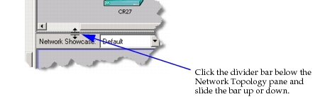
Note: To hide the Network Showcase, repeat one of the above tasks.
-
Creating a Showcase
A project scenario can include multiple showcases.
Procedure 67: Creating a Showcase
-
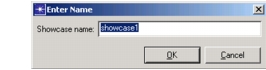
From the Showcase pull-down menu, select New…
Result: The Enter Name dialog box appears.
-
Enter the name for the new showcase and click OK.
Result: The new showcase displays.
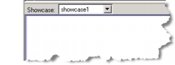
The showcase is empty until you feature objects in it. (See Featuring Objects in a Showcase.)
Copying a Showcase
You can copy the contents of a showcase to a new showcase.The copy option is useful when you want to create a new showcase that is similar to an existing showcase. The copied showcase includes all objects and configuration settings defined in the original showcase.
Procedure 68: Copying a Showcase
-
From the Showcase pull-down menu, select the showcase that you want to copy.
-
From the Showcase pull-down menu, select Duplicate…
Result: The Enter Name dialog box appears.
-
Enter the name for the copied showcase and click OK.
Result: The copy of the showcase with the specified name displays.
For more information, see:
Renaming a Showcase
You can rename a showcase. The rename option is helpful when you want to give a showcase a name that better identifies the featured objects.
Procedure 69: Renaming a Showcase
-
From the Showcase pull-down menu, select the showcase that you want to rename.
-
Perform one of the following:
- From the Showcase pull-down menu, select Rename…
- Right-click on an empty space in the showcase and choose Rename This Showcase…
Result: The Enter Name dialog box appears.
-
Enter the new name for the showcase and click OK.
Result: The showcase is renamed.
Note: The Default showcase cannot be renamed. If you select the rename option when the Default showcase is displayed, the system prompts for a new name and copies the showcase to a new showcase with the specified name. For more information, see Copying a Showcase.
For more information, see:
Deleting a Showcase
When a showcase is no longer useful, you can delete it.
Procedure 70: Deleting a Network Showcase
-
From the Showcase pull-down menu, select the showcase that you want to delete.
-
Perform one of the following:
- From the Showcase pull-down menu, select Delete…
- Right-click on an empty space in the showcase and choose Delete This Showcase…
Result: A confirmation dialog box appears to confirm the deletion.
-
Click OK.
Result: The specified showcase is deleted.
Note: The Default showcase cannot be deleted. To clear the contents of the Default showcase, see Removing Featured Objects from a Showcase.
Displaying a Showcase in a Floating Window
For a better view, you can display the contents of a showcase in a floating window. A typical showcase floating window is shown in Figure 49 and Figure 51.
After a showcase is displayed in a floating window, you can continue to define the showcase and the objects featured in the showcase. The showcase floating window displays until you either close the window or select the showcase from the Showcase pull-down menu. A showcase cannot appear in more than one place at the same time.
Procedure 71: Displaying a Showcase in a Floating Window
-
Perform one of the following
- Choose View > Open Network Showcase Window > <showcase name>, where <showcase name> is the name of the showcase that you want displayed in a floating window.
- Right-click on an empty space in the showcase and choose Open In Window.
Result: The showcase displays in a floating window.
To display the contents of the floating window in the Network Showcase pane, right-click on an empty space in the floating window and choose Show Inside Editor.
Note: The Default showcase cannot be displayed in a floating window. If you select the Open In Window option when the Default showcase is displayed, then before displaying the network objects in a floating window, the system prompts for a new name and copies the network objects to a showcase with the specified name. For more information, see Copying a Showcase.
Featuring Objects in a Showcase
There are many methods for specifying a featured object in a showcase:
-
Select an Object and Specify the Showcase Name
In the Network Topology or Network Showcase, right-click on an object and choose Featured In Showcase > <Network Showcase name>.
Note—
- If a showcase name is dimmed and not selectable, then that showcase is configured to exclude objects of that object's type as featured objects. For more information, see Defining Network Object Types to Feature.
- Selecting an already checked showcase stops featuring that object in the specified showcase.
-
Select the Object Checkbox in the Network Browser
In the Network Browser, click an object checkbox to feature the object in the active showcase. (See Figure 49.) If not already displayed, the Network Showcase is automatically shown when an object checkbox is selected in the Network Browser. When the Network Showcase is automatically shown for the first time in a scenario, the Default showcase is displayed.
-
Change an Associate Object to a Featured Object
- In a showcase, double-click on an associate object.
- In a showcase, right-click on an associate object and choose Feature In This Showcase.
- In the Network Showcase, Network Topology, or Network Browser, select one or more associate objects. Then right-click on an empty space in the showcase and choose Feature Selected Objects.
-
Use the Auto-Feature Mode
The Auto-Feature mode allows you to feature objects in the current showcase by simply selecting objects in the Network Topology or Network Browser. For more information, see Automatically Featuring Selected Network Objects.
For more information, see:
Removing Featured Objects from a Showcase
You can remove one or more featured objects from a showcase, as described in the following procedures:
- Removing a Single Featured Object from a Showcase
- Removing Multiple Feature Objects from a Showcase
- Removing All Objects from a Showcase
Procedure 72: Removing a Single Featured Object from a Showcase
-
Right-click on the object that you want to remove from the showcase and select Stop Featuring In This Showcase.
Result: The selected object is removed from the showcase.
Procedure 73: Removing Multiple Feature Objects from a Showcase
-
Select the objects that you want to remove from the showcase. Use one of the following methods:
- Hold down the Control key and click on the objects that you want to remove.
- Hold down the left-mouse button and draw a selection box around the objects that you want to remove.
-
Right-click on an empty space in the showcase and choose Stop Featuring Selected Objects.
Result: The selected objects are removed from the showcase.
Procedure 74: Removing All Objects from a Showcase
-
Right-click on an empty space in the showcase and choose Stop Featuring All Objects.
Result: All objects are removed from the showcase.
Selecting Featured Objects in a Showcase
When an object is selected in the showcase, it is also selected in the Network Topology and Network Browser. You can select one or more objects in the showcase to perform an action on the objects (i.e., edit attributes). Selecting objects in a showcase is similar to selecting objects in the Network Topology and Network Browser.
Perform one of the following actions to select object(s) in a showcase:
- To select a single object, click on the object.
- To select multiple objects, hold down the Control key and click on the objects that you want to select. Or, hold down the left-mouse button and draw a selection box around the objects you want to select.
- To select all featured objects, right-click on an empty space in the showcase and choose Select Featured Objects.
Exporting a Featured Object Set and Configuration Settings
Exporting featured objects saves a list of the featured objects to a file for future use. Additionally, the export includes configuration settings (i.e., types to feature, associations to show, auto-feature network selection mode, layout effect, and background color). The export featured object file can be imported into the same scenario or a different scenario to quickly re-create a particular showcase.
Procedure 75: Exporting a Featured Object Set
-
From the Showcase pull-down menu, select the showcase that you want to export the featured objects and configuration settings from.
-
Right-click on an empty space in the showcase and choose Export Featured Set.
Result: The Save As dialog box appears.
-
Specify the name and location of the export file and choose Save.
Result: The export file is saved in the specified location.
For more information, see:
Importing a Featured Object Set and Configuration Settings
Importing featured objects and configuration settings quickly re-creates a particular showcase.
The Network Showcase includes two types of imports:
- Importing Configuration Settings and a Featured Object Set into a New Showcase – Imports configuration settings (types to feature, associations to show, auto-feature network selection mode, layout effort, and background color) and a set of featured objects into a new showcase.
- Importing a Featured Object Set into an Existing Showcase – Imports only the set of featured objects. Featured objects already defined in the showcase are retained. Configuration settings are not imported.
Note: Regardless of the import type, only objects defined in the current project scenario are imported. If an object is in the featured object set file but is not defined in the current project scenario, then that object is not included in the showcase.
Procedure 76: Importing Configuration Settings and a Featured Object Set into a New Showcase
-
From the Showcase pull-down menu, select Import…
Result: The Import Showcase dialog box appears.
-
Locate and select the featured object set file that you want to import and choose OK.
Result: The Enter Name dialog box appears.
-
Enter the name of the showcase.
The new showcase appears containing the configuration settings and featured objects from the selected import file.
Procedure 77: Importing a Featured Object Set into an Existing Showcase
-
From the Showcase pull-down menu, select the showcase to which you want to import featured objects.
-
Right-click on an empty space in the showcase and choose Import Featured Set.
Result: The Import Selection File dialog box appears.
-
Locate and select the featured object set file that you want to import and choose OK.
Result: The featured objects are imported into the showcase.
For more information, see:
Defining Network Object Types to Feature
You can define the network object type(s) that can be featured (added) in each showcase in a scenario. If a network object type is not selected, then that object type cannot be featured (added) in the showcase as a featured object.
Procedure 78: Defining the Network Object Types to Feature in a Showcase
-
Right-click on an empty space in the showcase and choose Types To Feature.
-
Select one or more of the options:
- Nodes
- Links
- Paths
- Demands
- Subnets
Note: When a subnet is featured, the subnet contents are not automatically featured. To feature all objects in a subnet, see Selecting Featured Objects in a Showcase.
By default, Nodes, Links, Paths, and Demands are selected.
Note: When you unselect an object type, all objects of that type are removed from the showcase.
Defining Network Object Types to Associate with Featured Objects
You can define the network object type(s) that can be included in each showcase as objects associated with featured objects. Associate objects appear as minimized objects. Additionally, for node objects, you can specify the number of hops to include for associate node objects.
Procedure 79: Defining the Network Object Types to Associate with Featured Objects in a Showcase
-
Right-click on an empty space in the showcase and choose Associations To Show.
-
For nodes, select one of the following:
- Attached Nodes – Indicates to not include associate node objects.
- And Nodes 1 Hop Away – Indicates to include associate node objects up to 1 hop away from the featured object. By default, this option is selected.
- And Nodes 2 Hops Away – Indicates to include associate node objects up to 2 hops away from the featured object.
- And Nodes 3 Hops Away – Indicates to include associate node objects up to 3 hops away from the featured objects.
-
For objects other than nodes, select one or more of the following:
- Attached Links – Indicates to include associate link objects. By default, this option is selected.
- Attached Paths – Indicates to include associate path objects.
- Attached Demands – Indicates to include associate Demand objects.
Automatically Featuring Selected Network Objects
The Auto-Feature mode allows you to specify feature objects in the current showcase by simply selecting the object in the Network Topology or Network Browser. The Auto-Feature mode is useful when you have many objects to add to a showcase.
Procedure 80: Automatically Featuring Selected Network Objects in a Showcase
-
From the Showcase pull-down menu, select the showcase to which you want to feature (add) objects.
-
Right-click on an empty space in the showcase and choose Auto-Feature Network Showcase.
Result: The showcase outline changes from blue to red.
-
In the Network Topology or Network Browser, click on the object that you want featured in the showcase. To add multiple objects, hold down the Control key and click on the objects. (Click an object again to unselect it.)
-
After adding featured objects, turn off the mode by right-clicking on an empty space in the showcase and choose Auto-Feature Network Showcase.
Note: When Auto-Feature mode is turned on, you cannot select objects in the showcase pane. You can only select objects in the Network Topology and Network Browser.
Defining Layout Effort
When a network object is "featured" (added) in a showcase, the system tries to produce an esthetically pleasing layout. You can define the level of effort used to produce the layout for each showcase in a scenario.
Procedure 81: Defining the Layout Effort for a Showcase
-
From the Showcase pull-down menu, select the showcase for which you want to define layout effort.
-
Right-click on an empty space in the showcase and choose Layout Effort.
-
Select one of the options:
- No Effort
- Small Effort
- Normal Effort
- Large Effort
Note: "Large Effort" may impact performance, depending on the number of objects in the showcase.
Result: The objects in the showcase are automatically repositioned using the specified effort.
Defining a Background Color for a Showcase
You can define the background color of each showcase. Defining a background color can make the showcase easier to see and differentiates it from other showcases.
Procedure 82: Defining the Background Color of a Showcase
-
From the Showcase pull-down menu, select the showcase for which you want to define a background color.
-
Right-click on an empty space in the showcase and choose Background Color.
-
Choose one of the options:
- Use Default – Change the background color in the showcase to the default color. The default color is defined by the "ui_colors.tool_back" preference.
- Use White – Changes the background color in the showcase to white.
- Choose… – Displays the Color dialog box from which you can select a predefined or custom color for the showcase background.
Result: The background color of the showcase is changed to the selected color.
Applying a Predefined Network View to a Showcase
You can apply an existing network view to a showcase.
Procedure 83: Applying a Predefined Network View to a Showcase
-
From the Showcase pull-down menu, select the showcase to which you want to apply a predefined network view.
-
Perform one of the following:
- Right-click on an empty space in the showcase and choose View. Then choose a view option.
- From the View pull-down menu, choose a view option.
Choose Default View to display Showcase objects in the default view (no applied network view).
Result: The showcase incorporates the specified view.
After applying a network view to a showcase, you can also display the legend associated with the network view, if applicable. For more information, see Displaying Legend Information Associated with a Network View.
Displaying Legend Information Associated with a Network View
After applying a network view to a showcase (Applying a Predefined Network View to a Showcase), you can display the visualization legend, if applicable, in the showcase.
Procedure 84: Displaying Legend Information Associated with a Network View in a Showcase
-
From the Showcase pull-down menu, select the showcase for which you want to display the legend information associated with the applied network view.
-
Right-click on an empty space in the showcase and choose Show View Legend.
Result: If the applied view includes a legend, the legend appears in the showcase.
Applying the Network Topology Visualization to a Showcase
After applying a view to the network shown in the Network Topology, you can apply the same view to the network shown in a showcase.
Procedure 85: Applying the Network Topology Visualization to a Showcase
-
From the Showcase pull-down menu, select the showcase to which you want to apply the visualization used in the Network Topology.
-
Right-click on an empty space in the showcase and choose Overlay Topology’s Visualizations.
Result: The visualization applied in the Network Topology is applied to the showcase.
Network Showcase Pop-Up Menu
The following table lists the Network Showcase pop-up menu operations.
Table 39: Network Showcase Pop-Up Menu
| Option | Description |
|---|---|
| Feature Selected Objects | Features (adds) the selected objects in the active showcase. For more information, see Featuring Objects in a Showcase. |
| Stop Featuring Selected Objects | Removes the selected featured objects from the active showcase. For more information, see Removing Featured Objects from a Showcase. |
| Stop Featuring All Objects | Removes all featured objects from the active showcase. For more information, see Removing Featured Objects from a Showcase. |
| Select Featured Objects | Selects all "featured" objects in the active showcase for performing an action on them. For more information, see Selecting Featured Objects in a Showcase. |
| Export Featured Set | Exports a list of featured objects from the active showcase. The list of exported objects can be imported to quickly re-create a showcase. For more information, see Exporting a Featured Object Set and Configuration Settings. |
| Import Featured Set | Imports a list of featured objects into the active showcase to quickly re-create a showcase. For more information, see Importing a Featured Object Set and Configuration Settings. |
| Types To Feature | Defines the network object type(s) that can be featured (added) in the active showcase. For more information, see Defining Network Object Types to Feature. |
| Associations To Show | Defines the network object type(s) that can be included in the active showcase as objects associated with featured objects. For more information, see Defining Network Object Types to Associate with Featured Objects. |
| Auto-Feature Network Selection | Allows you to add "featured" objects to the active showcase by simply selecting objects in the Network Topology or Network Browser. For more information, see Automatically Featuring Selected Network Objects. |
| Layout Effort | Defines the effort requested for producing an aesthetically pleasing layout in the active showcase. For more information, see Defining Layout Effort. |
| Background Color | Defines the background color of the active showcase. For more information, see Defining a Background Color for a Showcase. |
| View | Applies a predefined view to the active showcase. For more information, see Applying a Predefined Network View to a Showcase. |
| Show View Legend | Displays the visualization legend, if applicable, in the active showcase. For more information, see Displaying Legend Information Associated with a Network View. |
| Overlay Topology’s Visualizations | Applies the Network Topology’s visualizations to the active showcase. For more information, see Applying the Network Topology Visualization to a Showcase. |
| Open in Window Show Inside Editor |
Displays the active showcase in a floating window. Right-click in a floating window and select Show Inside Editor to display the showcase in the Network Showcase. For more information, see Displaying a Showcase in a Floating Window. |
| Rename This Showcase… | Renames the active showcase. For more information, see Renaming a Showcase. |
| Delete This Showcase… | Deletes the active showcase. For more information, see Deleting a Showcase. |