Node Editor
In a local area network (LAN), each computer plus its network interface is a node within the network. In a satellite network supporting television broadcasting, each satellite is a node; other nodes in the network include the TV stations that originate the broadcast signals, earth stations with satellite dishes that perform satellite uplink and downlink, and microwave and cable-based relay stations that provide for local boosting and re-transmission of the signals. In a private corporate telephone network, each building or facility with its own PBX might be considered a node.
In general terms, a node is a facility or resource in which data either originates and is transmitted, or is received and processed, or both. From this definition, it follows that a node has at least some of the following internal capabilities in relation to messages and data that messages contain:
- creation
- transmission
- reception
- storage
- internal routing
- internal processing, modification, and/or enhancement (such as content analysis, queuing, multiplexing, and error detection and correction)
Typically, a node has both hardware and software components that support these capabilities.
The Node Editor provides the resources necessary to model the internal functioning of nodes. Within the Node Editor, you can access different modules. Each kind of module serves to model some internal aspect of node behavior, such as data creation, data storage, data processing or routing, data transmission, etc. A single node model is usually comprised of multiple modules—sometimes dozens or even hundreds of modules.
Connecting the modules are packet streams and statistic wires. Packet streams carry packets of data between modules in a node. Statistic wires provide the ability for one module to monitor a varying quantity within another module. The combined use of modules, packet streams, and statistic wires provides the ability to create highly realistic simulations of node behavior. Additionally, you can specify that specific receivers and transmitters be treated as a tightly-associated pair of modules.
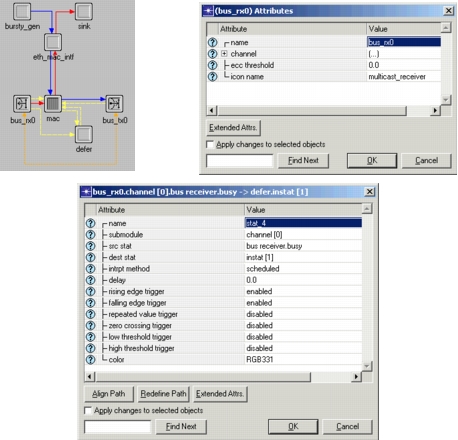
The following figure shows an example of a typical node model. In addition to the model itself, the figure shows the dialog boxes used to edit attributes of objects, such as modules and statistic wires.
Figure 182: Node Model and Related Dialog Boxes
For more information about node modeling techniques, see “Node Domain” on page 263.