Importing Topologies from CSV Text Files
NetPlanner supports importing topologies from comma-separated values (CSV) text files. Follow these basic steps:
- Define the nodes in one or more CSV text files and the links in one or more other CSV text files.
- Save both sets of them to a directory that NetPlanner can access.
- Specify the “Directory Containing Source CSV” files by choosing: Topology > Import Topology > From CSV Text Files.
Key Concept—The node and link definition files include required columns to specify the node names, the interface port technologies you want to use such as Ethernet, E1, or GigabitEthernet, and the number of ports and links you want to model in your network. Several optional header fields help you provide more details to your network topology.
Figure 1: CSV Text Files for Importing Network Topologies
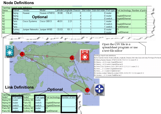
Tip: Develop a strategy of specifying nodes and links in as many CSV text files as you want—NetPlanner imports all the CSV files in the source directory to the opened scenario. Use the Example Steps in the next section as a guide for your topology import using CSV files.
How does NetPlanner specify interface names for specific vendors?
NetPlanner uses a default interface naming convention specification file that determines the exact strings used for each interface name.
As you plan your topology import using CSV files, consider the naming conventions you want to use for the interfaces in your imported network. The default interface naming conventions used by NetPlanner for typical vendor configurations work fine in many cases.
Key Concept—You can customize the naming conventions used for specific vendors or a use case that you identify by modifying an existing naming convention or adding a new interface naming convention.
For more information, see Specifying Interface Naming Conventions and Custom Names for Interface Types.
Example Steps to Import Topology Using CSV Files
Step 1—Set Up Directory for Topology and Interface Naming Files
Before you can import topologies using CSV files or take advantage of naming conventions that you want to specify, you must create a shared network or local directory that NetPlanner can access.
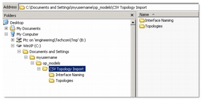
For example, create a Topologies directory and an Interface Naming directory in op_models, as shown in the following figure.
Figure 2: Example Directories
Step 2—Create Topology Node Files in CSV Format
Use the following node definitions to create topology node files in CSV format:
Table 1: Node Definition Fields
| Name | Inclusion | Description |
|---|---|---|
| Name | Required | Specify the name of the node you want to use in the network model |
| Subnet | Optional | Specify the name of the subnet where you want the node located in the network (subnets create the hierarchical network levels in your network projects) |
| Vendor | Optional | Specify the vendor name used for the node model you want to create in the imported network |
| Model | Optional | Specify the model name for the vendor model you want to create in the imported network |
| Latitude | Optional | Specify the Latitude to place the imported node in a geographical location |
| Longitude | Optional | Specify the Longitude to place the imported node in a geographical location |
| Chassis | Optional | Specify the chassis name for the node that you want to create in the imported network |
| Slot index | Optional | Specify a unique slot index and associated sub-slot index to define multiple interfaces on the node |
| Sub-slot index | Optional | Specify the sub-slot index for the unique slot index, sub-slot index combination for interfaces on the node |
| Port type | Optional | Specify the type of port that you want to include on the imported node (for example, router or switch) |
| Port technology | Required | Specify the interface technology for the number of ports specified in the next field |
| Number of ports | Required | Specify how many ports you want configured as attributes in the imported node model |
Tip: Base your topology files on existing example files shipped with NetPlanner, such as the one shown in the following example and located in the following directory: <install_dir>\models\module_ref\csv_import\multi_vendor_import
Example Node Definitions
Define the first row of a node with all the fields that you want to use and then subsequent rows must include the subnet name and the other unique optional and required fields.
Topology import node definitions,,,,,,,,,,,
Name,Subnet,Vendor,Model,Latitude,Longitude,Chassis,Slot index,Sub-slot index,Port type,Port technology,Number of ports
CPZ1,CPZ,Cisco Systems,Cisco C6513,32.76,-83.42,3,1,0,router,10GEthernet,20
CPZ1,CPZ,,,,,3,2,0,router,10GEthernet,20
CPZ1,CPZ,,,,,3,2,1,router,10GEthernet,20
CPZ1,CPZ,,,,,4,3,0,router,OC192,1
CPZ1,CPZ,,,,,4,3,1,router,OC192,1
CPZ2,CPZ,Huawei,Huawei CX600,33.76,-84.42,3,1,0,router,10GEthernet,20
CPZ2,CPZ,,,,,3,2,0,router,10GEthernet,20
CPZ2,CPZ,,,,,3,2,1,router,10GEthernet,20
CPZ2,CPZ,,,,,4,3,0,router,OC192,1
CPZ2,CPZ,,,,,4,3,1,router,OC192,1
DNJ1,DNJ,Juniper Networks,Juniper M160,41.285,-104.39,3,1,0,router,10GEthernet,20
DNJ1,DNJ,,,,,3,2,0,router,10GEthernet,20
DNJ1,DNJ,,,,,3,2,1,router,10GEthernet,20
DNJ1,DNJ,,,,,4,3,0,router,OC192,1
DNJ1,DNJ,,,,,4,3,1,router,OC192,1
Step 3—Create Topology Link Files in CSV Format
Use the following Link definitions to create CSV topology files to connect the defined nodes in your imported network.
Table 2: Link Definition Fields
| Name | Inclusion | Description |
|---|---|---|
| Node1 | Required | Specify the node name defined in the node definition file that you want as the first endpoint for the link |
| Subnet1 | Optional | Specify the name of the subnet defined in the node definition file for Node1 |
| Port type1 | Optional | Specify the port type such as router or switch for the link |
| Node2 | Required | Specify the node name defined in the node definition file that you want as the second endpoint for the link |
| Subnet2 | Optional | Specify the name of the subnet defined in the node definition file for Node2 |
| Port type2 | Optional | Specify the port type such as router or switch for the link |
| Port technology | Optional | Specify the port technology for the link such as OC12 or Ethernet |
| Number of links | Optional | Specify how many links you want configured as attributes between the imported nodes |
Tip: Similar to the node definition examples, base your link topology files on existing files shipped with NetPlanner, as shown in the following example and located in this directory: <install_dir>\models\module_ref\csv_import\multi_vendor_import
Example Link Definitions
Node1,Subnet1,Port type1,Node2,Subnet2,Port type2,Port Technology,Number of Links
CPZ1,CPZ,router,CPZ2,CPZ,router,OC192,2
DNJ1,DNJ,router,DNJ2,DNJ,router,OC192,2
CPZ2,CPZ,router,GNJ2,GNJ,router,10GEthernet,8
DNJ1,DNJ,router,HSJ2,HSJ,router,10GEthernet,3
Note: Port type1 and Port type2 are optional fields
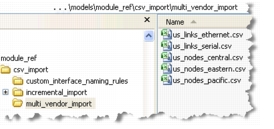
To view the CSV files used in these examples, navigate to the following installed directory and open them using a text editor.
Figure 3: Shipped Example CSV Topology Files
Step 4—Import the Topology from CSV Files
To create a network model with your configured CSV files, open an existing or new project in NetPlanner. Choose to use the startup wizard if applicable or the Topology menu and then choose the option to Import Topology From CSV Text Files.
Specify the directory you created for the topology files in the first step along with the other settings, as shown in the following figure.
Figure 4: Example Import Configuration
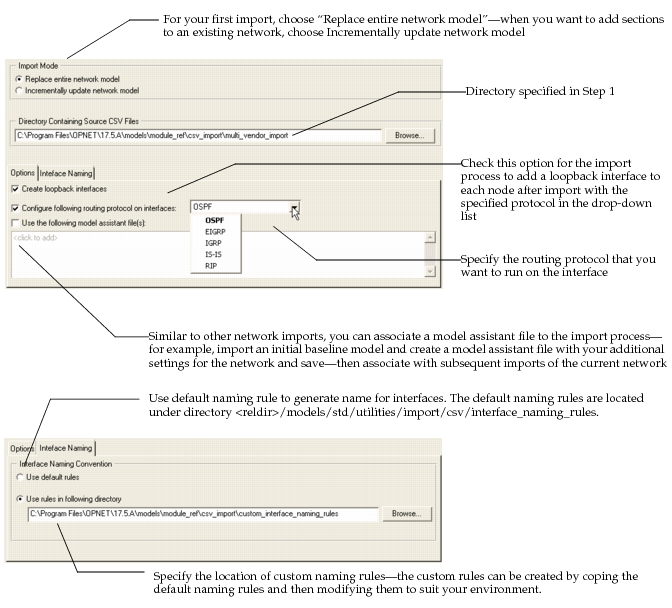
Click “Import” and then view your resulting network model. In some cases you might want to modify or add an interface naming convention as described in the next section.
Note: During the import process, NetPlanner assigns an icon from the shipped icon database using the vendor model and icon entry in the vendor node mapping file, as shown in the following figure.
Figure 5: Node Model Mapping File
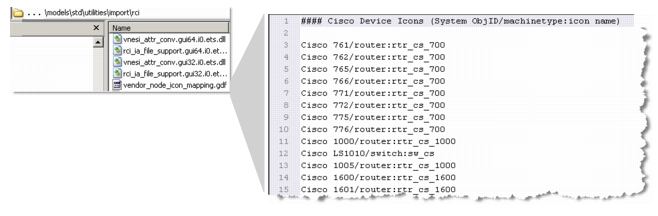
If necessary, you can modify this file to add new mappings for specific vendors. Remember to backup this file up before reinstalling the same version of the software to make sure you do not lose your customization.
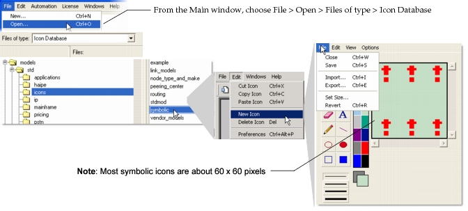
You can add new icons to an existing or new icon database by creating or importing an image that you want to use. You can access the Icon Database editor, as shown in the following figure.
Figure 6: Using the Icon Database