Background Operations
Backgrounds (both maps and images) represent real-world entities that are fixed in space. They provide a physical context for your network models, allowing you to interpret them more easily.
The basic difference between maps and images is that maps represent large-scale geographic entities and are described by latitude and longitude coordinates. Three different types of maps are recognized: border maps, image maps, and MIF maps.
Images represent small-scale entities, such as office floor plans, and are described by referencing points on an x-y axis.
Set Border Map…
Border maps use vector lines to define political and geographic areas such as East Asia, France, and California, using latitude-longitude coordinates to specify positions. Riverbed Modeler includes a library of border maps. Border maps are visible in every subnet and cannot be edited.
Procedure 47: Placing a Border Map
-
Verify that your network model is set to the appropriate scale (World, Enterprise, Campus, Office, Logical, or map-specific). When you use the Startup Wizard, you can select the scale for the network. You can modify the scale of an existing model with the Set Background Properties operation (see Set Background Properties).
-
Display the subnet in which you want to place the map and zoom to the approximate area.
-
Choose View > Background > Set Border Map…
Result: The Choose Border Map dialog box appears.
-
Select the desired map.
Result: The map is placed in your network model.
Add Image Map…
Image maps comprise a bit-mapped image that is tied to specific latitude-longitude coordinates. Such maps provide a more graphically detailed background than do border maps. (For background images of smaller extent, such as floor plans, see Add Image….) Image maps are visible only in the subnet in which they are placed.
Two image map formats can be imported:
- GeoTIFF – GeoTIFF files include latitude and longitude information, which are used to place the map in the correct position.
- TIFF – TIFF files do not include latitude and longitude information. When a TIFF files is imported, the project editor switches to map edit mode allowing you can enter latitude and longitude data.
Imported image map files are stored with a .map.i extension.
Riverbed Modeler includes pre-imported image maps, which appear in the list presented by the View > Background > Add Image Map command. The image maps were created by the U.S. Geological Survey. You can get additional images of this type from the Web, at http://terraserver.microsoft.com.
You can also find other maps on the Internet; these maps are often in .gif format. You must convert such images to TIFF or GeoTIFF format before importing them.
The following procedures describe two tasks:
For information about editing an image map, see Map Edit Mode.
Once placed in a network model, image maps can be hidden by using the Show Maps in Subnet operation (on the View > Background menu).
Procedure 48: Placing an Already-Imported Image Map
-
Verify that your network model is set to the appropriate scale (World, Enterprise, Campus, Office, Logical, or map-specific). When you use the Startup Wizard, you can select the scale for the network. You can modify the scale of an existing model with the Set Background Properties operation (see Set Background Properties).
-
Display the subnet in which you want to place the map and zoom to the precise area.
-
Choose View > Background > Add Image Map…
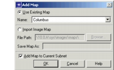
Result: The Add Map dialog box appears.
Figure 33: Add Map dialog box
-
Verify that the Use Existing Map radio button is selected.
-
Verify that the Add Map to Current Subnet checkbox is selected.
-
Select the desired file name.
Result: The map is placed in your network model, centered in the workspace.
Procedure 49: Importing an Image Map
-
Verify that your network model is set to the appropriate scale (World, Enterprise, Campus, Office, Logical, or map-specific). When you use the Startup Wizard, you can select the scale for the network. You can modify the scale of an existing model with the Set Background Properties operation (see Set Background Properties).
-
Display the subnet where you want to place the map and zoom to the approximate area. You may want to import a border map to use as reference.
-
Choose View > Background > Add Image Map…
Result: The Choose Map dialog box appears.
-
Click the Import radio button.
-
Verify that the Add Map to Current Subnet checkbox is set appropriately. You can import a map for later use even if you do not want to include it in the current scenario.
-
Do one of the following:
- Type the path name of the file you want to import and enter a file name in the Save Map As field.
- Click on the Browse button, select the file you want to import, and verify that the file name in the Save Map As field is acceptable.
-
Click OK.
Result: The file is saved in the first directory listed in your “mod_dirs” preference.
The image is placed in the workspace.
-
If the image is a GeoTIFF file, the latitude and longitude specifications in the file are used to place the image map in the correct geographic position. The view may scroll so the map can be seen. A message in the message display area lists the geographic area covered by the map.
-
If the image is a TIFF file, the Set Location and Size dialog box appears. See Map Edit Mode for details on this dialog box.
At this point, you have two options: the better option is to determine and enter the correct latitude and longitude specifications for the map image. If you do this, the map is placed correctly the next time it is imported.
The other option is to exit map edit mode, import a border map, and—using the border map as a guide—place your image map in approximately the correct location.
-
Add MIF Map…
MIF maps are text files of geographic information in the MapInfo Interchange File format created by MapInfo Corporation. Maps in this format are available from a variety of sources and mapping programs. The MIF specification can be downloaded from the MapInfo Corporation website at http://www.mapinfo.com.
Riverbed Modeler uses MIF files with a .mif extension (which are the files that contain geographic information). The directory containing the MIF files must be listed in the “mod_dirs” preference. Modeler imports version 3.0 MIF files that use a global coordinate system with units of degrees. If other coordinates are used in the file or if the MIF file is a later version (4.0–7.8), Modeler tries to import the file, with the following possible results:
- Some items might be skipped or handled differently. These include:
- Collections (drawn as individual items)
- Multipoints and text (displayed)
- Tables using MS Access databases (skipped)
- Interleaved line styles or objects (skipped)
- Datums, ellipsoids, and projections released after version 3.0 (skipped)
- The map might display incorrectly or not at all.
If problems occur during import, a dialog box summarizes the problems. Details can be seen by clicking the View Log button in the dialog box. The log for the most recent MIF import is saved in your op_admin directory. Previous MIF import logs are moved to the op_admin/tmp directory.
MIF maps are imported as separate layers in the workspace (as described in Object Layering). You can rearrange, hide, or remove them by choosing View > Background > Set Properties.
Procedure 50: Importing a MIF Map
-
Display the subnet where you want to place the MIF map and zoom to the approximate area. (You may want to import a border map to use as reference.)
-
Choose View > Background > Add MIF Map…
Result: A list of available MIF files appears.
-
Click the file name of each map you want to add to the workspace.
Result: Each map is placed in the subnet as you click its name. If the file cannot be imported completely, a dialog box opens summarizing the problems found.
Note: MIF data usually covers a limited area. Unless that area is visible in the subnet, you will not see imported maps until you zoom into that area.
-
When you are finished adding maps, click Close.
Add Image…
Images must be a bit-mapped graphic in TIFF format. They typically represent a small-scale, real-world area such as an office floor plan. (For background images of larger extent, such as a city map, see Add Image Map….) Images are visible only in the subnet in which they are placed.
When you place an image, the project editor automatically switches to map edit mode for you to adjust the image position or size. Imported image files are stored with a .bkg.i extension.
The following procedures describe two tasks:
For information about editing an image, see Map Edit Mode.
After being placed in a network model, images can be hidden using the operation View > Background > Show Maps in Subnet.
Procedure 51: Placing an Image in a Network Model
-
Verify that your network model is set to the appropriate scale for the background image (Enterprise, Campus, or Office). When you use the Startup Wizard, you can select the scale for the network. You can modify the scale of an existing model with the Set Background Properties operation (see Set Background Properties).
-
Choose View > Background > Add Image…
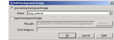
Result: The Add Background Image dialog box appears.
Figure 34: Add Background Image Dialog Box
-
Verify that the Use Existing Background Image radio button is selected.
-
Select the desired background image.
Result: The map is placed in your network model, centered in the workspace and editing mode is turned on. See Map Edit Mode for details.
Procedure 52: Importing an Image
-
Choose View > Background > Add Image…
Result: The Add Background Image dialog box appears.
-
Select the Import Background Image radio button.
-
Do one of the following:
- Type the path name of the file you want to import and enter a file name in the Save Background As field.
- Click on the Browse button and select the file that you want to import.
-
Click OK to save the file.
Result: The file is saved (with an extension
.bkg.i) in the first directory listed in your “mod_dirs” preference.The project editor changes to editing mode. You can exit the editing mode by choosing View > Background > Map Edit Mode, or you can edit the background image. See Map Edit Mode for details.
Map Edit Mode
Map edit mode allows you to modify both image maps and images. In this mode, you can:
- Change the location of a map or image. “Location” means the position of the map or background image within the subnet.
- Change the size of a map or image.
- Cut, copy or paste a map or image from one scenario to another, or within the same scenario.
Procedure 53: Editing a Map or Image
-
Choose View > Background > Map Edit Mode. (The project editor changes automatically to this mode after some operations.)
-
Select the map or image by clicking on it.
Result: Handles appear around the map or image.
-
Edit the map or image as desired, using techniques described in the following table.
Table 34: Edit Map or Image Operations
To… Instruction Cut, copy, or paste. Choose the desired operation from the Edit menu.
When you paste a map or image to a different scenario, make sure the scale of the destination scenario matches the scale of the source scenario. You cannot, for example, paste the map of France into a scenario that is measured in feet.
You typically copy a map or image to a different scenario, but you can paste multiple copies in the same scenario.Resize a map or image Use either of two methods:
• Drag one of the handles on the map.
• Modify the attributes in the Set Location and Size dialog box, as described in step 4 to step 6.Move a map or image Use either of two methods:
• Drag the object to the desired position.
• Modify the attributes in the Set Location and Size dialog box, as described in step 4 to step 6. -
To resize (or move) a map or image, right-click on it.
Result: The Map pop-up menu appears.
-
Choose Set Location and Size from the pop-up menu.
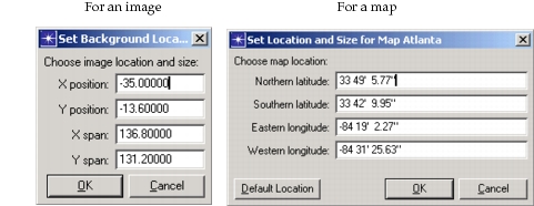
Result: The Set Location and Size dialog box displays. This dialog box varies, depending on whether the object to be modified is an image or a map.
Figure 35: Set Location and Size Dialog Box
-
Follow the appropriate step:
- To resize an image – modify the X Span (width) and Y Span (height) attributes and click OK. The unit of measure is the same unit of measure as used for the subnet (degrees, kilometers, feet, and so on).
- To resize a map – modify the latitude and longitude attributes.
- To move an image – modify the X Position and Y Position attributes.
- To move a map – modify the latitude and longitude attributes.
-
Choose View > Background > Map Edit Mode to exit Map Edit mode.
Object Layering
Layering is used to separate objects in the workspace. Each type of object (such as a node, grid line, or map) is drawn on a particular layer, with objects in higher layers overlaying—and possibly obscuring—those in lower ones. When objects of different types overlap, the frontmost object is the one that is highest in the object type hierarchy. The default hierarchy—from front to back—is as follows:
- Network objects (nodes, links, paths, and annotations)
- Grid lines
- MIF maps
- Satellite orbits
- Vector (border) maps
- Background maps and images
You can change this hierarchy using the View > Background > Set Properties operation. (See Set Background Properties.)
In addition, within the network objects layer, each type of object exists in a sub-layer with other similar objects. This hierarchy is:
- Paths (see text)
- Nodes (including subnets)
- Links and paths
- Annotations
Thus, for example, links will always appear behind nodes and in front of annotations. If objects of the same type overlap, you can specify which object will appear in front by using the Bring to Front or Send to Back operation from the Object pop-up menu. These operations move the selected object within its sub-layer, relative to all other objects of its type.
Paths are treated in a special way with regard to layering, as follows:
- When created or moved to the front, a path overlays all other network objects, including nodes.
- When moved to the back, a path moves to the back of the link and path sub-layer.