Importing Baseline Load Traffic—ASCII Text File Format
NetPlanner can import baseline loads from text files. Table 13 lists the steps to do before you import data. After you do these steps, proceed to Creating Baseline Load Text Files.
Table 13: Preparing for an Import: Baseline Load Text Files
| Step | When Required | Reference |
|---|---|---|
| Specify aliases | Once per scenario. Required for nodes or links that meet both these conditions: - Were created manually - Are referenced by the imported data |
“Working with Aliases“ |
| Create data files | As needed | Creating Baseline Load Text Files - “gbu” File Format - “gbu2” File Format |
| Import baseline loads from MTR files | As needed | Importing Baseline Loads from MTR Files |
Creating Baseline Load Text Files
You can create baseline load data files in any standard text editor; a file should use one of the formats shown in “gbu” File Format or “gbu2” File Format. These formats differ in how they specify baseline loads:
- The .gbu format specifies each baseline load as a percentage of the total available bandwidth on the link (“Value %” field). The background load is calculated using this field and the total link bandwidth.
- The .gbu2 format specifies each baseline load as a throughput in bits per second (“Value (bps)” field)
Format Guidelines
Observe these guidelines:
-
Each text file has two sections: a node section and a link section. The node section must appear before the link section.
-
The keywords “Nodes” and “Links” are required in .gbu files; the keywords “Nodes” and “Links” are required in .gbu2 files.
-
Entries in each field must be separated by one tab character.
-
Aliases are associated with actual objects in your network, and are described in detail in “Working with Aliases“.
-
For nodes, the value of the Attribute field must be the actual attribute name specified in the underlying model: for example, “CPU Background Utilization.”
-
For .gbu files, the value for the Time field must be specified in seconds. For .gbu2 files, you can also specify time using the formats shown in Figure 47.
-
In the Links section, the Value field specifies the throughput level on the link object. This load is expressed as either a percentage of the total link throughput (.gbu format) or an absolute throughput in bits per second (.gbu2 format).
-
The Direction field appears only in the Links section. Valid values for the Direction are
-
BOTH: The imported traffic is traveling in both directions.
-
A: The imported traffic is transmitted from node A to node B.
-
B: The imported traffic is transmitted from node B to node A.
To determine node A and node B, right-click on a link and choose Edit Ports. The Select Port Assignment dialog box lists node A first and node B second.
-
-
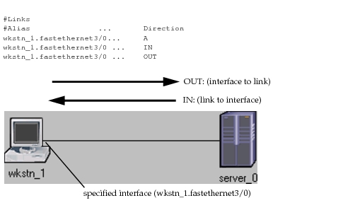
The .gbu2 format supports two additional options for the Direction field:
Figure 45: Direction Fields in GBU Files: Example
“gbu” File Format
This format specifies link utilization as a percentage of total link utilization, and is compatible with previous releases (Release 10.0.A and earlier). All fields are tab-separated.
Note: In NetPlanner releases prior to 10.0, most link models had an attribute called “link utilization,” which specified link utilization as a percentage of the total available bandwidth. In NetPlanner 10.0, this attribute was replaced by the “link load” attribute, which specifies traffic in bits per second (bps) and packets per second (pps). When you import a .gbu file that was created prior to release 10.0, the import engine translates the utilization data into traffic loads based on the total available bandwidth on the affected link.
Figure 46: General Background Utilization “gbu” File Format
Nodes
#Alias    Attribute                        Time (sec)    Value %
CA        CPU Background Utilization       300           20
DE        CPU Background Utilization       3800          80
MN        CPU Background Utilization       7600          100

Links
#Alias    Attribute                        Time(sec)     Value %    Direction
link-CA   Background Utilization           100           40         A
link-DE   Background Utilization           200           50         B
link-DE   Background Utilization           400           60         B
link-CA   Background Utilization           600           20         A
link-MN   Background Utilization           900           99         B
“gbu2” File Format
You can use .gbu2 files to apply baseline loads on nodes, links, LSP/PVC connection objects. This format specifies each link and PVC load as a fixed throughput, and is compatible with later releases (10.0.A and later). This version is not supported in earlier releases (10.0.A and earlier). All fields are tab-separated.
Figure 47: Baseline Load “gbu2” File Format
Specify baseline loads for nodes:
Nodes
#Alias			Attribute									Time (sec)							Value %
CA			CPU Background Utilization									0							20
DE			CPU Background Utilization									19:40:30 Jan 14 2006							80
MN			CPU Background Utilization									20:15:00 Jan 14 2006							100
#Specify baseline loads for links, LSPs, and PVCs:
Links
#Alias						Time					Value (bps)		 		Avg Frame Size					Direction				[Traffic Class]
“ArlingtonR01.FastEthernet0/3/3"	19:40:30 Jun 14 2014	  25,276		227.200078	 OUT	   Gold
“ArlingtonR01.FastEthernet0/3/3"	19:45:30 Jun 14 2014	  undefined	 250.349583	 OUT					Gold
“ArlingtonR01.FastEthernet0/3/3"	19:40:30 Jun 14 2014	  19,541		227.200078	 IN					Gold
“ArlingtonR01.FastEthernet0/3/3"	19:45:30 Jun 14 2014	  undefined	 293.149583	 IN	  				Gold
Importing Baseline Loads from MTR Files
Table 14: “gbu2” Baseline Load File Format
| Item | Description |
|---|---|
| Nodes | Required keyword indicates the start of the nodes definition section. |
| - Alias | Node alias. To determine the correct alias to use, right-click on the link or connection object and choose Edit Aliases. For more information about aliases, see “Working with Aliases“. |
| - Attribute | Model attribute of the node that specifies the baseline load |
| - Time (sec) | Load start time. Each entry in this table has a start time and a background load. The load level applies until the start time of the next entry. The final entry applies to the end of simulation. You can enter relative times, which are offsets from the network start time (for example, “30” for 30 seconds after the start time), or calendar times. If you specify calendar times, use the following format: hh:mm:ss Mmm dd yyyy (for example, “19:40:30 Jan 14 2006”) |
| - Value % | The percentage of total processing time that the node spends running background jobs. |
| Links | Required keyword indicates the start of the links/LSP/PVC definition section. |
| - Alias | Alias of the node and the node interface (for link and LSP loads) or subinterface (for PVC loads). This alias should be in the format - <node_alias_on_connected_node>.<interface_alias> [link and LSP loads]- <node_alias_on_connected_node>.<subinterface_alias> [PVC loads]To determine the correct alias to use, right-click on the link or connection object and choose Advanced Edit Attributes, and click the appropriate “Interface Aliases” button. Note: If the required node, interface, or subinterface interfaces are not specified on corresponding link/LSP/PVC, the import engine cannot match the specified load to its corresponding object. Therefore, you might need to add interfaces manually in order to import the load data. the For more information about aliases, see “Working with Aliases“. |
| - Time | Load start time. Each entry in this table has a start time and a background utilization. The background load applies until the start time of the next entry. The final entry applies to the end of simulation. You can enter relative times, which are offsets from the network start time (for example, “30” for 30 seconds after the start time), or calendar times. If you specify calendar times, use the following format: hh:mm:ss Mmm dd yyyy (for example, “19:40:30 Jan 14 2006”) |
| - Value (bps) | Traffic intensity for the specified time window, in bits per second. |
| - Average Frame Size | Average frame size of the specified traffic, in bytes. |
| - Direction | Direction of the baseline traffic. Valid values for this field are - IN – The imported traffic is traveling into the interface (specified in the Alias field) from the link, as shown in Figure 45. - OUT – The imported traffic is traveling out of the interface into the link, as shown in Figure 45. - BOTH – The imported traffic is traveling in both directions. - A – The imported traffic is transmitted from node A to node B. - B – The imported traffic is transmitted from node B to node A. - To determine node A and node B, right-click on a link and choose Edit Ports. The Select Port Assignment dialog box lists node A first and node B second. |
| Traffic Class | Class of Service (CoS) specified for traffic on link |
During data export, NetCollector creates separate ASCII files for each traffic metric and saves the files with the .mtr extension. These MTR files are imported when you include metric data during an import from NetCollector, but you can also import MTR files from a directory, using the Traffic > Import Baseline Loads > From Text Files... menu option. Simply specify the location of the MTR files you want to import and click Import.
Figure 48: Import Baseline Loads from ASCII Files

For more information, see “Verifying a Baseline Load Import“.