Layout Operations
The Layout submenu provides several operations for controlling the way nodes and subnets are displayed in the workspace. Operations include
- Automatic Icon Scaling
- Automatic Label Placement
- Scale Node Icons Interactively
- Geographic Positioning
- Lay Out Nodes Interactively
- Lay Out Nodes (Balanced)
- Lay Out Nodes (Simple)
- Lay Out Nodes (Core-Centric)
- Lay Out Nodes (Circular)
- Lay Out Nodes (Hierarchical)
- Lay Out Nodes (Schematic)
Automatic Icon Scaling
The Project Editor window can resize node icons automatically to reduce overlapping and visual clutter. The “icon_autosizing.disable” preference controls whether this feature is on or off. To turn automatic icon resizing on or off from the menu bar, choose View > Layout > Automatic Icon Scaling.
Because automatic icon sizing in large networks can slow down performance, autosizing is turned off if the node count reaches or exceeds the threshold specified by the “icon_autosizing.large_element_count” preference.
Automatic Label Placement
The Project Editor window can move node labels automatically to reduce overlapping. If there is no space to show the node label, it is hidden unless the node is selected. To turn automatic label placement on or off, choose View > Layout > Automatic Label Placement. You can control where the label is placed with the “title_autoplacing.directions” preference. To allow automatic label placement to use smaller fonts, use the “title_autoplacing.try_small_font” preference.
Scale Node Icons Interactively
This operation enables you to scale the icon size of one or more sites. For example, if an icon is 12 x 12 pixels at full size, you can scale the icon to 50% so that it appears at half-size (6 x 6 pixels) at most.
If you scale an icon below a certain size, the icon becomes minimized—that is, it appears as a simple shape rather than as a bitmap. To specify the size of the shapes used and the threshold at which bitmap icons are replaced by shapes, choose View > Edit Display Preferences.
Figure 38: Scaling a Node Icon
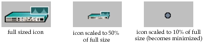
Procedure 55: Scaling One or More Node Icons
-
Select the nodes whose icons you want to scale. To scale all node icons in a scenario, left-click in the network background to ensure that no nodes are selected.
-
Choose View > Layout > Scale Node Icons Interactively.
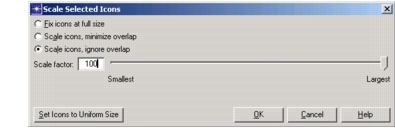
Result: The Scale Selected Icons dialog box appears.
Figure 39: Scale Selected Icons Dialog Box
-
Scale the selected icons by the desired amount.
- To scale all icons to their full size (as defined by the icon bitmaps), select the “Fix icons at full size” radio button.
- To scale all icons to a specified percentage of their current size, select the “Scale icons” radio button; then use the slider to set the percentage.
- To scale all selected icons to the same size (that is, to the current size of the smallest icon in the selection set), click the “Set Icons to Uniform Size” button.
-
Click the Preview button to see the results of the current settings. If you don’t like the results, change the scaling options and click Preview again.
-
Click OK to apply the setting.
Geographic Positioning
The positioning mode determines how objects are arranged in the Project Editor workspace. There are two positioning modes:
- The geographic positioning mode shows network objects according to their geographic locations.
- The non-geographic positioning mode allows objects to be placed anywhere in the Project Editor workspace, regardless of their physical locations.
To switch modes, choose View > Layout > Geographic Positioning. This menu item shows a checkmark when the geographic positioning mode is enabled.
Geographic Positioning Mode
The geographic positioning mode shows network objects by their physical locations. Each node, subnet, and configuration utility object has two advanced attributes (“x position” and “y position”) that determine its geographic position. Each link object has a defined physical path; a path can contain multiple segments.
The geographic positions and paths of objects are not affected by the current view.
Non-Geographic Positioning Mode
The non-geographic positioning mode allows objects to be placed anywhere in the Project Editor workspace, regardless of their physical locations. Each network view can have its own layout, so a view can arrange objects in a way that makes sense to that view. (For more information about network views, see Set View for Subnet/Network.)
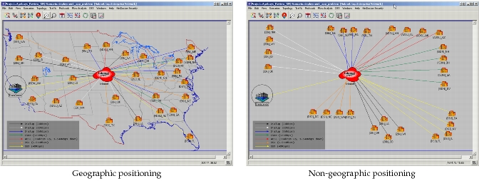
A non-geographic layout can add visual clarity to your network. For example, you can use a non-geographic layout when nodes are too close together to distinguish at a specific zoom level. Or you can arrange objects to emphasize certain characteristics of the network. The following figure shows a network that connects several buildings located throughout the United States. These buildings use various types of connections. In the non-geographic mode, the buildings are arranged by connection type: dial-up, ISDN, ADSL, and so on.
Figure 40: Geographic vs. Non-Geographic Positioning: Example
Object Positions in Geographic and Non-Geographic Mode
Each node, subnetwork, and configuration utility object has exactly one geographic position, as determined by its “x position” and “y position” attributes. Because each network view can specify its own non-geographic layout, an object can have multiple non-geographic positions in addition to its geographic position.
Note: When you move or place objects, the changes apply to the current layout mode and view only. If you move an object while in geographic mode—that is, while View > Layout > Geographic Positioning is enabled—the change affects the object’s geographic position only. If you move an object while in non-geographic positioning mode, the change affects the current view only.
By default, a view inherits its layout from the geographic locations of the objects in that view. This means that unless a view specifies otherwise, the view shows an object at its physical position.
You can display selected nodes in the other mode’s position:
- If in geographic mode, choose View > Layout > Move Selected Nodes To Non-Geographic Positions.
- If in non-geographic mode, choose View > Layout > Move Selected Nodes To Geographic Positions.
Lay Out Nodes Interactively
The Layout Nodes Interactively operation enables you to expand, contract, or rotate objects in a network display to improve visual clarity on the screen. To perform this operation, follow these steps.
Procedure 56: Using Interactive Layout to Adjust the Network Display
-
Choose View > Layout > Lay Out Nodes Interactively...
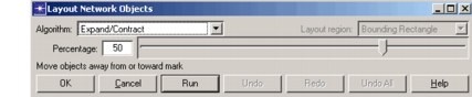
Result: The Layout Network Objects dialog box appears.
Figure 41: Layout Network Objects Dialog Box
-
From the Algorithm drop-down menu, select the desired interactive layout option (Expand/Contract is the default option).
See Table 35 for a description of the interactive layout options.
-
Select the objects on which you want to operate.
Result: A special green cross icon initially appears in the center of your selection set. This is the “mark” icon for the Expand/Contract and Rotate algorithms.
-
Drag the mark icon to the point on the screen where you want to anchor the selected group of objects during the layout operation.
-
For the Disperse algorithm, specify the layout region within which that algorithm will operate.
-
Click Run.
-
Repeat Steps 3 through 6, as needed.
Each iteration will add an “undoable” command to the local Undo stack. To un-do the previous layout operation, click Undo. To re-do the last Undo operation, click Redo. To put all objects in the position of their initial values (when the Layout Network Objects dialog box first opened), click Undo All.
-
Click OK.
The Layout Network Objects dialog box provides the following options.
Table 35: Network Layout Options
| Algorithm Name | Description |
|---|---|
| Expand/Contract | Moves selected objects away from or toward the green cross “mark” icon |
| Expand/Contract Horizontally | Moves selected objects away from or toward the mark icon horizontally |
| Expand/Contract Vertically | Moves selected objects away from or toward the mark icon vertically |
| Rotate | Rotates (by degrees) the selected objects in a counter-clockwise direction around the mark icon |
| Disperse | Moves selected objects within the specified layout region away from each other |
Lay Out Nodes (Balanced)
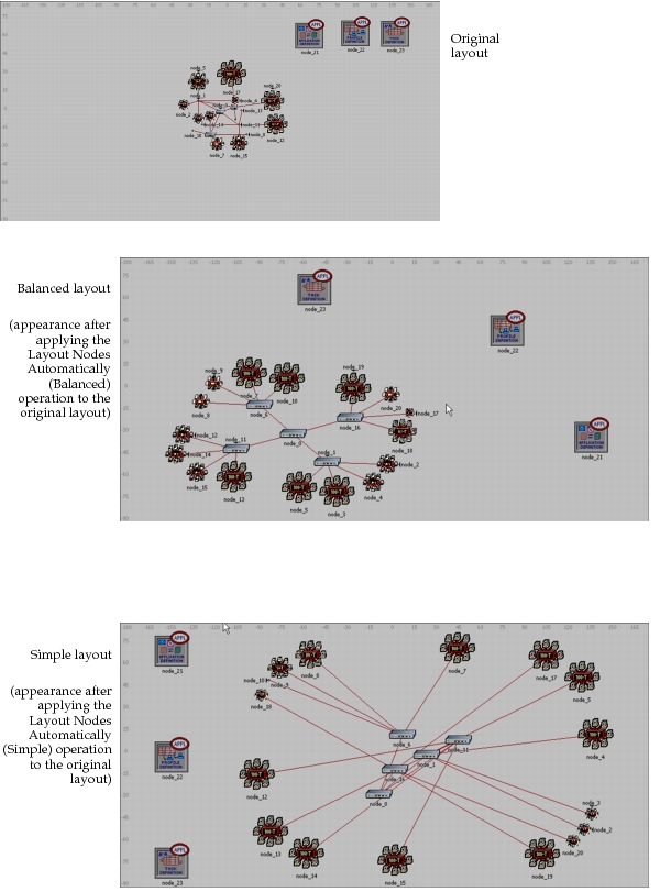
When you choose View > Layout > Lay Out Nodes (Balanced), the sites in the current subnet are repositioned, trying to produce an aesthetic layout. (See Figure 42 for an example.) This operation can make a crowded network easier to work with and is faster than manually repositioning sites. You can control which sites are moved as follows:
- If no sites are selected, every site in the current subnet is considered for repositioning.
- If one or more sites are selected, only the selected sites are considered for repositioning.
If there are unconnected groups of sites in the subnet, this operation also balances the spacing between the groups. This step can be disabled with the “network_layout.adjust_unconnected_groups” preference.
Lay Out Nodes (Simple)
When you choose View > Layout > Lay Out Nodes (Simple), the sites in the current subnet are repositioned, trying to produce an illustrative, but not necessarily aesthetic layout. (See Figure 42 for an example.) The algorithm used by this operation is faster and uses less memory than the balanced algorithm used by the Lay Out Nodes (Balanced) operation. Thus, it is better for subnets with large numbers of sites.
Figure 42: Automatic Node Layout Examples
Lay Out Nodes (Core-Centric)
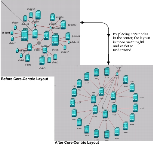
The core-centric Layout operation (View > Layout > Lay Out Nodes (Core Centric)…) allows you to create a meaningful network layout, based on core nodes. The layout places core nodes in the center. All other nodes are placed around the core nodes based on the quantity of links. Nodes attached to the network with only one link are placed furthest from the core nodes. Nodes with no link attachments to the network are placed on the left side of the workspace.
The following figure shows an example of a core-centric layout. Before the core-centric layout is applied (shown in the upper-left of the figure), the layout is arbitrary. However, after the core-centric layout is applied (shown in the lower-right of the figure), the layout is more meaningful with core nodes placed in the center of the arrangement. The core-centric layout operation is even more useful with larger networks.
Figure 43: Core-Centric Layout (Example)
Core nodes are determined using one of the following methods:
- Select Core Nodes with Most Connections – Core nodes are determined based on the quantity of links. Nodes with the highest quantity of links are designated as core nodes.
- Use Selected Nodes – Select one or more nodes, subnets, and/or utility objects. Selected objects are designated as core nodes.
Procedure 57: Applying a Core-Centric Layout
-
Enter the subnet to which you want to apply a core-centric layout.
-
Choose View > Layout >Lay Out Nodes (Core Centric)…
Result: The Core Centric Layout dialog box appears.
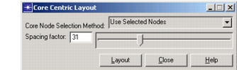
Figure 44: Core Centric Layout Dialog Box
-
Specify the requested information:
- Core Node Selection Method – Specifies the method for selecting core nodes. If no nodes are selected, “Select core nodes with most connections” displays. If one or more nodes are selected, “Use Selected Nodes” displays.
- Spacing factor input field/slider – Specifies the spacing of the layout (0-100). The higher the spacing factor, the more compressed the layout. Specify a spacing factor by either entering a number in the input field or using the slider bar.
-
Select the Layout button.
Result: The layout is applied to the current subnet.
See Figure 43 for an example core-centric layout.
Lay Out Nodes (Circular)
When you choose View > Layout > Lay Out Nodes (Circular), the nodes in the current subnet are repositioned to produce a circular network layout that shows interconnected ring and star topologies. The circular layout emphasizes group and tree structures with a network.
Lay Out Nodes (Hierarchical)
When you choose View > Layout > Lay Out Nodes (Hierarchical), the nodes in the current subnet are repositioned to produce a hierarchical layout that shows a precedence relationship. The hierarchal layout emphasizes flow.
Lay Out Nodes (Schematic)
When you choose View > Layout > Lay Out Nodes (Schematic), the nodes in the current subnet are repositioned to produce a schematic layout with right-angled links. The overlapping of links is kept to a minimum, depending on the size and complexity of the network.