Shared Risk Groups
A shared risk group defines a failure relationship between two sets of network objects, where failures in one set cause failures in the other set. Shared risk groups are useful for modeling dependency relationships such as the following:
- Several links that depend on a fiber: if the fiber fails, the links also fail
- A power source for a building: if the power source fails, all nodes in that building fail
Every shared risk group has three components:
-
risk element set – contains one or more network objects that other objects (those in the impacted element set) depend on to function.
-
impacted element set – contains one or more network objects that depend on objects (those in the risk element set) to function.
Risk element sets and impacted element sets can contain nodes, links, and other risk groups.
-
failure propagation criterion – defines the conditions under which failures in the risk element set cause failures in the impacted element set.
You can use risk groups to model risk factors that can cause failures in a production network but do not exist as actual objects in the network model. To do this, you can create a risk group in which the risk element set is empty and the impacted element set contains objects that depend on the “missing” object. To model the failure, fail the group directly (as described in Procedure 122). Scenarios where this technique might be useful include:
- Fiber cuts – To model a fiber cut, create a shared risk group and give it a name like “fiber_1”. The impacted element set includes all links that depend on that fiber. To model a fiber cut, fail the group “fiber_1” so that the impacted links also fail.
- Power failures – To model a power failure, create a shared risk group and give it a name like “power source 1”. The impacted element set includes all nodes that depend on that power source. To model a power failure, fail the group “power source 1” so that the impacted nodes also fail.
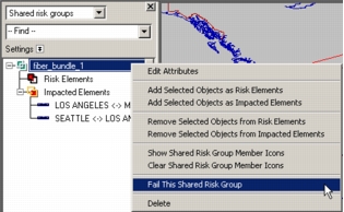
After creating risk groups, you can view and edit them in the Network Browser, as shown in the following figure.
Figure 90: Shared Risk Groups in the Network Browser
Creating Shared Risk Groups Manually
The following procedure describes how to create a risk group in the Project Editor.
Procedure 121: Creating a Risk Group Manually
-
Verify that all the network objects you want to specify as risk elements and impacted elements are present in the scenario.
-
In the Project Editor window, choose Topology > Shared Risk Groups > New.
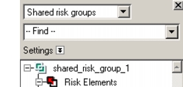
- The Network Browser opens, with the View filter menu set to Shared Risk Groups. A new risk group appears in the treeview.
-
To rename a risk group, right-click on the group, choose Edit Attributes, and set the “name” attribute.
-
Add the risk elements (if any):
-
4.1 Select the nodes, links, and risk groups that you want to include in the risk element set. (If you want to select a risk group, you must select it in the Network Browser because risk groups are not visible in the Project Editor workspace.)
-
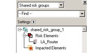
4.2 In the Network Browser treeview, right-click on the risk group and choose Add Selected Objects as Risk Elements.
- The selected objects are added under Risk Elements.
-
-
Add the impacted elements to the group:
-
5.1 Select the nodes, links, and risk groups that you want to include in the impacted element set. (If you want to select a risk group, you must select it in the Network Browser because risk groups are not visible in the Project Editor workspace.)
-
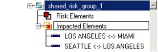
5.2 In the Network Browser treeview, right-click on the risk group and choose Add Selected Objects as Impacted Elements.
- The selected objects are added under Impacted Elements.
-
-
Specify the failure propagation criterion for the risk group:
- 6.1 Right-click on the risk group and choose Edit Attributes.
- The Attributes dialog box for the shared risk group appears.
- 6.2 For the “failure propagation criterion” attribute, specify one of the following settings:
- Any Risk Element Failed – All impacted objects are disabled if any member of the risk element set is disabled.
- All Risk Elements Failed – All impacted objects are disabled only if all members of the risk element set are disabled.
- 6.3 Close the Edit Attributes dialog box.
- 6.1 Right-click on the risk group and choose Edit Attributes.
Failing and Recovering a Shared Risk Group
The following procedure describes how to fail a risk group; Procedure 123 describes how to recover a risk group.
Procedure 122: Failing a Risk Group
-
If the Network Browser is not open, choose View > Show Network Browser.
-
Set the View filter to Shared Risk Groups.
- The Network Browser treeview shows all shared risk groups in the scenario.
-
Each risk group has an advanced attribute called “condition,” which specifies its failure status. You can fail a shared risk group using either of the following methods:
- Right-click on the risk group and choose Fail this Shared Risk Group
- Risk-click on the risk group, choose Edit Attributes, check the Advanced checkbox, and set the “condition” attribute to “disabled”.
Procedure 123: Recovering a Failed Risk Group
-
If the Network Browser is not open, choose View > Show Network Browser.
-
Set the View filter to Shared Risk Groups.
- The Network Browser treeview shows all shared risk groups in the scenario.
-
Each shared risk group has an advanced attribute called “condition,” which specifies its failure status. You can fail a shared risk group using either of the following methods:
- Right-click on the risk group and choose Recover this Shared Risk Group
- Right-click on the risk group, choose Edit Attributes, check the Advanced checkbox, and set the “condition” attribute to “enabled”
Visualizing the Operational Status of Shared Risk Group Elements
To see which network objects are members of a failed risk group, choose Topology > Shared Risk Groups > Visualize Operational Status > Visualize. An icon displays over every network object that is currently failed due to its membership in a risk group. To clear the risk-group visualizations, choose Topology > Shared Risk Groups > Visualize Operational Status > Clear.
Note: If any risk-group elements are failed or recovered while status visualization is enabled, the visualization status does not refresh automatically; you must choose Topology > Shared Risk Groups > Visualize Operational Status > Visualize again to update the visualization.
Creating Data Files for Shared Risk Groups
You can create a data file for shared risk groups using one of the following methods:
- Export the shared risk groups defined in an existing scenario by choosing Topology > Shared Risk Groups > Export. If desired, you can edit the resulting file in a text editor.
- Define one or more shared risk groups in a text file with an extension of “srgi”.
After you create a data file, you can import the risk group definitions into a scenario (as described in Procedure 124).
Figure 91: Data File with Definitions of Shared Risk Groups
start_riskgroup_creation
	name: My Risk Group 1
	risk element: top.Kansas City.router5
	risk element: top.Denver.router4
	impacted element: top.Kansas City.router4 <-> top.Denver.router5
	failure propagation criterion: Any
end_riskgroup_creation

start_riskgroup_creation
	name: My Risk Group 2
	risk element: top.Denver.router5 <-> top.Seattle.server1
	risk element: top.Denver.router5 <-> top.Portland.server4
	impacted element: top.Denver.router4
	failure propagation criterion: All
end_riskgroup_creation
Table 54: Data File Format for Shared Risk Groups
| Field | Description |
|---|---|
| start_riskgroup_creation | Start of the definition for this risk group |
| name: | Name of the risk group |
| risk element: | To specify one or more risk elements, a line has the following format: - “Risk Element” string at the beginning of the line - A colon (‘:’) character. To make the file more readable in a spreadsheet, you can add tab characters before and after the colon. - A tab-delineated list of network objects |
| impacted element: | To specify one or more impacted elements, a line has the following format: - “Impacted Element” string at the beginning of the line - A colon (‘:’) character. To make the file more readable in a spreadsheet, you can add tab characters before and after the colon. - A tab-delineated list of network objects |
| failure propagation criterion: | The failure criteria can be one of the following: - Any – All impacted objects are disabled if any member of the risk element set is disabled. - All – All impacted objects are disabled only if all members of the risk element set are disabled. |
| end_riskgroup_creation | End of the definition for this risk group |
Importing Data Files for Shared Risk Groups
The following procedure describes how to import shared risk groups from a data file into a scenario.
Procedure 124: Importing a Data File for Shared Risk Groups
- Create a data file using one of the following methods:
- Export the shared risk groups defined in an existing scenario by choosing Topology > Shared Risk Groups > Export… If desired, you can edit the resulting file in a text editor.
- Define one or more shared risk groups in a text file using the format described in Creating Data Files for Shared Risk Groups.
- Copy the file into one of your model directories.
- In the Project Editor window, choose Topology > Shared Risk Groups > Import…
- The Select Import File dialog box appears.
- Select the data file you want to import and click OK.