Exporting Network Information
Available export operations include:
- Export Network to XML
- Export Network to Visio
- Export to Bitmap/Generate Scenario Bitmap
- Export Network to Spreadsheet
Export Network to XML
The Export to XML operation produces an XML file that contains all of the characteristics of your network topology. The resulting XML file can be viewed and edited in any XML editor. You can access the attributes of a model from one source without opening the attributes of each node from the user interface.
Procedure 55: Exporting Network Topology to an XML File
-
Choose Topology > Export Topology > To XML…
Result: The generated XML file is structured according to the network topology Document Data Type (DTD). The DTD file, network.dtd, is located in the
<install_dir>\<release>\sys\etc\directory.
Export Network to Visio
The Export to Visio operation creates Visio .vdx (Visio XML drawing) and .vsx (Visio XML stencil) format files that can be viewed and edited in Visio 2003.
Note: If Visio is installed on a different machine than Riverbed Modeler, download Microsoft Office Visio 2003 Viewer from http:/www.microsoft.com/downloads to view exported Visio files.
Procedure 56: Exporting a Network to Visio
-
Choose Topology > Export Topology > To Visio…
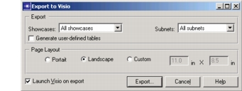
Result: The Export to Visio dialog box appears.
Figure 529: Export to Visio Dialog Box
-
Specify the requested information:
Table 226: Export to Visio Options
Option Description Export Showcases Specifies the showcase(s) to export. Choose one of the following:
• None
• Current showcase
• All showcasesSubnets Specifies the subnet(s) to export. Choose one of the following:
• None
• Current subnet
• All subnetsGenerate user-defined tables Specifies whether to export user-defined tables for generating reports. Page Layout Specifies the page layout orientation and size. Choose one of the following:
• Portrait – Specifies 8.5 x 11 inches.
• Landscape – Specifies 11 x 8.5 inches.
• Custom – Specifies a custom size. When selected, specify the height and width.Launch Visio on export Specifies to open the exported file automatically after exporting a file.
Note: The preference “diagram_prog” must be set with the path of the Microsoft Visio program. -
Click Export.
Result: The Export to Visio file selection dialog box appears.
-
Specify the file name, file type (.vdx or .vsx), and location for the file.
-
Click Save.
Result: The specified topology is exported to a Visio file. Also if selected, Visio opens and displays the exported Visio file.
Export to Bitmap/Generate Scenario Bitmap
The Export to Bitmap operation is active in the Project, Node, and Process Editors. It creates a bitmap image of a model. The operation differs slightly by editor: in the Project Editor, the operation (called Generate Scenario Bitmap) allows you to capture a subnetwork or a portion of a subnetwork. In the Node and Process Editors, you capture the entire node or process model.
Procedure 57: Exporting a Bitmap Image
-
Display the subnetwork, node model, or process model you want to capture.
-
(Project Editor only). If you want to capture only part of the subnetwork, adjust the zoom level so that the section you want to capture appears in the Project Editor window.
-
Choose the correct operation for the editor you are using:
- (Project Editor only). Choose Scenarios > Generate Scenario Bitmap…
- (Node and Process Editors). Choose File > Export To Bitmap…
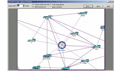
Result: The Model Image Capture Preview dialog box appears.
Figure 530: Model Image Capture Preview Dialog Box
-
Set the capture parameters. See Setting Capture or Print Parameters for details.
-
Click Save.
Result: The Select Captured Image Location dialog box appears.
-
Select the directory where the file will be saved. Type a file name (with a .gif or .tif suffix) in the Save as field and press
<Return>. You can also select the file format from the Filters menu, in which case the suffix is added automatically. See Capturing a Bitmap Image for details.Result: The object is scanned and stored in the specified directory and format.
Export Network to Spreadsheet
As you build and maintain complex models, you may need descriptions of the objects in the model, their attribute values, and the connections among them. You may also need to see this information at different levels of detail. Sometimes you will want a detailed report of each object and each object’s attribute. Other times a summary (just the number and type of each object, by subnet) is more helpful.
This operation (available in the Project Editor only) produces a report that can have a variable amount of detail, depending on what values you specify for certain preferences. If the spreadsheet_prog preference is configured correctly, the command also launches a spreadsheet program and displays the report.
The report is divided into four sections:
- Devices summary – This section lists the total number of nodes and the number (count) by device type.
- Links summary – This section lists the total number of links and the number (count) by link type.
- Device details – This section lists the name and device type of each node, organized by subnet.
- Link details – This section lists the name and link type of each link, organized by subnet.
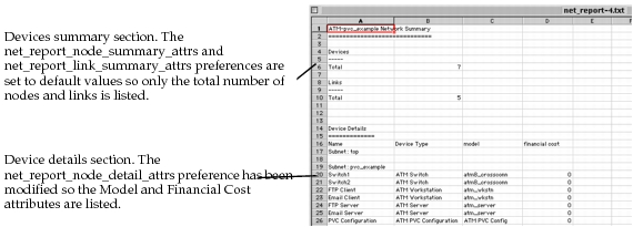
You can also modify certain preferences so the report lists additional information. A portion of a sample report is shown in the following figure.
Figure 531: Network Summary Report Sample
File Creation and Review
Each time you execute this command, a file is created in the temporary file directory of your administration directory (<HOME>/op_admin/tmp). Report names follow this format:
net_report-<sequence_num>.txt
Each execution of the command creates a sequentially-numbered file, even if the reports describe different models.
You can use either of two methods to review the report:
- View the report in Excel or another spreadsheet program. If the correct path name to the spreadsheet program is specified in the
spreadsheet_progpreference, the spreadsheet will launch automatically. - Open an edit pad and read in the desired file. The information is more difficult to interpret because the text cannot be arranged into neat columns. Use this method only if you do not have easy access to a spreadsheet program.
Procedure 58: Configuring and Exporting a Network Summary to a Spreadsheet Program
-
To view the resulting report in a spreadsheet program, verify that the “spreadsheet_prog” preference has the correct path name.
-
To see specific model attributes included in any part of the report, verify that the attributes are included by default, or modify the appropriate preferences:
- “net_report_node_details_attrs”
- “net_report_link_summary_attrs”
- “net_report_node_details_attrs”
- “net_report_link_detail_attrs”
To modify preferences, choose Edit > Preferences.
-
Choose Topology > Export Topology > To Spreadsheet…
Result: A file is created in the temporary file directory of your administration directory. If “spreadsheet_prog” is correctly configured, the spreadsheet program launches and displays the report. You will probably need to adjust the column widths so data is fully displayed. If you do not have access to a spreadsheet program, choose Edit > Open Edit Pad, then open the file.