Printing or Capturing from the GUI
This section describes procedures for capturing a bitmap image of all or part of the screen, printing the network model, and using the preview screen to configure the capture or print operation.
- Previewing a Capture or Print Operation
- Capturing a Bitmap Image
- Printing Network Information
- Printing and File Handling
Previewing a Capture or Print Operation
When you choose any print operation or the Export to Bitmap/Generate Scenario Bitmap operation, the preview window displays and lets you set certain parameters. The dialog boxes for export and for print differ slightly. The following procedure describes the options in each dialog box.
Procedure 52: Setting Capture or Print Parameters
-
Display the model you want to export or print.
-
Choose the desired operation.
- For more information about printing, see Printing Network Information.
- For more information about capturing a model as a bitmap, see Export to Bitmap/Generate Scenario Bitmap.
Result: Depending on the operation, either the Print Preview or Model Image Capture Preview dialog box displays.
Figure 527: Print Preview Dialog Box
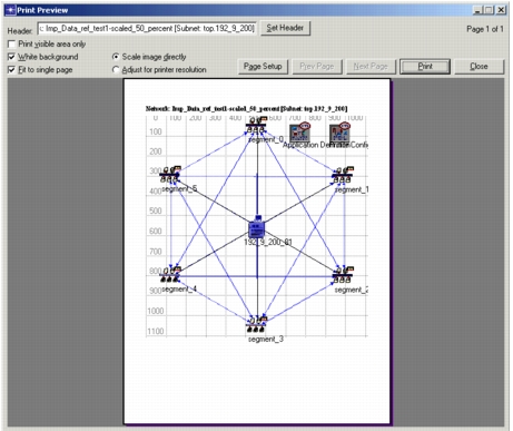
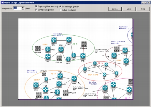
Figure 528: Model Image Capture Preview Dialog Box
The dialog boxes include the following components:
- Capture/Print Visible Area Only checkbox – With this box checked, only the area visible in the window is captured or printed. With this box unchecked, the entire subnetwork or model is captured or printed.
- Fit to Single Page – Prints the entire model on one page.
- Image Width – Use the up and down arrows to adjust the bitmap width; Modeler adjusts the height accordingly.
- Next Page and Prev Page buttons – Allows you to scroll through the pages to be printed.
- Page Setup button – Select page size and orientation.
- Scale Image Directly/Adjust Resolution radio buttons – The Adjust Resolution setting causes Modeler to adjust the level of detail based on the target bitmap size—that is, it reduces the level of detail in smaller bitmaps and increases it in larger ones. This setting is most appropriate for small bitmaps of large and/or complex topologies and for very large bitmaps that allow for a maximum amount of detail. The Scale Image Directly setting results in bitmaps with the same level of detail as seen in the editor, regardless of the bitmap size.
- Set Header – Modifies the default header. Type the new header in the header field, then click this button. The new header is displayed. You can specify a different header for each page.
- White Background checkbox – Sets the background color to white, which can improve contrast and visibility.
-
Set the controls as desired and click Save… or Print.
Capturing a Bitmap Image
The Capture Bitmap operation makes it easy to capture an entire window or a region of a window as an image file.
Note: You can use this operation to capture an image of your network model, but the image will include the menu bar and button bar. The Export Network to Bitmap operation is typically a better choice when you want an image of the network topology. See Export to Bitmap/Generate Scenario Bitmap for details.
The Capture bitmap operation uses one of two file formats—Tagged Image File Format (TIFF or TIF) or Graphical Interchange Format (GIF). The GIF file format is the default.
- TIFF files are binary files that contain a compressed representation of the captured bitmap. TIFF files can easily be edited with many bitmap graphics programs.
- GIF files were originally developed to provide high-resolution images over the Internet. These images have been encoded and compressed; their small size lets you transfer them across a network easily. GIF files can be opened in many desktop publishing tools and are easily edited with many graphics programs.
Procedure 53: Capturing a Bitmap Image
-
Make the window you want to capture the active window.
-
Resize the window, if necessary, so that the entire area you want to capture is visible.
-
To capture the entire window, press
<Control>+t. To capture a region of the window, press<Control>+<Shift>+t, and then drag the cursor around the area you want to capture.- On Windows platforms, the standard file chooser dialog box appears.
- On Linux platforms, the Modeler file chooser dialog box appears.
-
Select the directory where the file will be saved. On Linux platforms, you can use the menu options to modify the display and navigate to the directory.
- Change which file types are displayed by selecting the desired file type from the Filters menu
- Change the ordering of items displayed by selecting the desired method from the View menu
- Select a particular directory from the History or Special menus
- Traverse the directory tree with the arrow buttons
-
Type a file name (with a .gif or .tif suffix) in the Save as Type field and press
<Return>.Note: You can also select the file format from the Filters menu, in which case the suffix is added automatically.
Result: The object is scanned and stored in the specified directory and format.
Printing Network Information
Print operations differ by editor. In the Project Editor you can print:
- the subnet displayed in the active window
- the entire model, including every subnet
In the other editors in which print operations are available, you can print only the entire model or file.
After choosing a print operation, the preview window displays and allows you to set parameters before printing the document.
Procedure 54: Printing a Model
-
Display the model or file you want to print.
-
Select the page size and orientation desired. Choose File > Page Setup… and select the parameters desired from the pop-up menu.
-
Choose the desired print command.
- (Project Editor only). To print the subnet displayed in the active window, choose File > Print…
- (Project Editor only). To print the entire model, including every subnet, choose File > Print All Subnets…
- (Other editors). To print the entire model or file, choose File > Print…
Result: The Print Preview dialog box appears.
-
Set the print parameters as desired.
For more information, see Setting Capture or Print Parameters.
-
Click the Print button.
Result: The Print dialog box appears.
-
Set the parameters as desired and click OK.
For more information, see “User Interface” on page 1.
Result: The model is printed.
Printing and File Handling
On Windows platforms, print spooling and color printing properties are determined by the native printer driver.
On Linux platforms, print spooling and color printing are handled differently. On these platforms, Modeler
- sends output files to the print spooling program specified by the preference
printcmd, typically a spooler such as the Linux utility lpr. You can also specify a different program or shell script for special purposes, such as suppressing all printing or moving output files to another location. - generates color PostScript files that print in color on color printers or in grayscale on monochrome printers.
Preferences specify the print spooler program invoked, the default printer, and the maximum number of pages that can be printed with one print request. See “Preferences” on page 30 for instructions on using preferences. For instructions on changing an preference, see “System Menus” on page 29.