Using Paths to Represent Virtual Circuits
You can create path objects between nodes or subnets. Any protocol model that uses logical connections or virtual circuits (such as MPLS) can use paths to represent traffic routes.
This section has the following subsections:
- What is a Path?
- Path Model Options
- Path Connectivity
- Other Path Options
- Creating a Path Object
- Path Pop-Up Menu Operations
What is a Path?
A path is a defined route between two sites; a site can be either a fixed node object or subnetwork. The process of defining a path is similar—though not identical—to defining a link. First, configure an object palette to include the path models you want; then select a model and click on objects in the Project Editor workspace to connect them.
Paths have no built-in simulation behavior: the underlying protocol models determine when and how to use a particular path. See the relevant model documentation for information about how particular models use paths.
Path Model Options
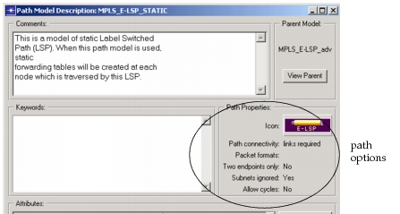
Each path model has a set of options that determine the path connectivity requirements and the types of objects that you can include in a path definition. You can view a model’s options in the Path Model Description dialog box, which you open by right-clicking on a model in the object palette. You should verify that the underlying model’s options allow you to create the type of path you want. If you cannot find a path model whose options exactly match the type of path you want to create, you may want to derive a new model from an existing one.
Figure 14: Path Model Description Dialog Box
Path Connectivity
A path object defines, at the very least, two end sites. It may also define a partial or complete path (that is, a set of connecting sites and links) between these sites. The “Path Connectivity” option defines the extent to which you can define the intermediate path. The three possible settings are:
- Links Required – In a required-link path, you must specify a simplex or duplex point-to-point link between every site in the path; all such links are included in the path definition.
- Links Ignored – In an ignored-link path, you can only include sites in the path definition. The underlying models fully determine routes between the included sites.
- Links Optional – This is a combination of the required-link and ignored-link types. You must define the head, tail and any intermediate sites, defining any connecting links between sites is optional.
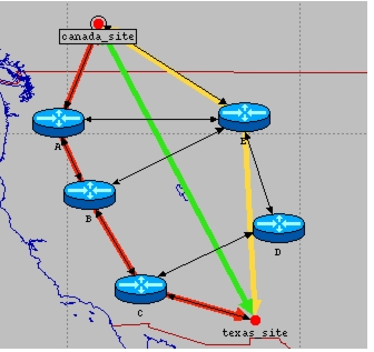
The following figure shows a router network that connects a site in Canada to a site in Texas. Traffic constrained by the required-link path (left) always follows the exact route defined between Canada and Texas. If the ignored-link path (center) defines a route, the underlying models fully route any traffic using this path. The optional-link path (right) defines a partial route that includes the link between Canada and router E; the underlying models route the traffic between router E and Texas.
Remember that in a situation like this, with multiple paths defined between the same two sites, the underlying models choose the actual path taken by a packet.
Figure 15: Multiple Paths Between Two Sites
Other Path Options
Other path options are:
- Packet Formats – Each path has a defined set of supported packet formats. You cannot define a link as part of a path unless that link supports all formats included in the path model’s Packet Formats field. (Note that if a path supports no packet formats, you can include any link in the path definition.)
- Two Endpoints Only – If this option is set to Yes, you can create single-segment paths only.
- Subnets Ignored – If this option is set to Yes, you cannot include a subnetwork object in a path definition. (However, you can still include nodes from different subnets in the same path.)
- Allow Cycles – If this option is set to No, you can only include each link or site once in a path definition.
Creating a Path Object
Procedure 7: Creating a Path Between Two Sites
-
If necessary, open an object palette and configure it to include the path models you want.
-
Left-click on a path model in the object palette to select it.
The cursor changes appearance to indicate that you are in path-creation mode.
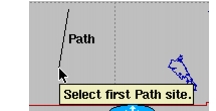
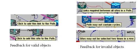
A path object’s underlying options (described in Path Model Options) determine the objects you can include in your path definition. In path-creation mode, an extensive visual feedback is provided to validate additions to your path. If you move the cursor over an invalid link or site, the cursor changes appearance and a tooltip appears to indicate why that choice is invalid.
Figure 16: Visual Feedback in Path-Creation Mode
-
Left-click on the site you want to define as the head of your path.
-
(Required-link and optional-link paths only): Left-click on any sites and links that you want to include in your path.
You must click on a link to include it in the path definition if
- You are defining a links-optional path;
- You are defining a links-required path and want to include two sites that have multiple links connecting them.
-
Repeat step 4 until you have clicked on the tail site and the path definition is complete.
-
Right-click in the project workspace and choose Finish Path Definition from the pop-up menu.
A unique name is assigned to the new path.
Note: After defining a path, you are still in path-definition mode. You can create another path (based on the same underlying model). To exit path-definition node, right-click and choose Abort Path Definition from the pop-up menu.
Path Pop-Up Menu Operations
Right-click on any demand object to open the Path pop-up menu.