Model Attribute Interfaces
The concept of a model’s attribute interfaces has already been loosely referred to. Strictly speaking, a model’s attribute interfaces does not encompass those attributes declared as model attributes, though both sets of attributes do contribute to the interface of the model. Model attributes are considered separately because they are declared and fully defined in one place. In contrast the model’s attribute interfaces represent modifications of other attribute definitions, as will be described in this section.
The attribute interfaces of a model consist of several fairly different types of components and so the name “attribute interfaces” can be confusing. These components are listed in the following table.
Table 30: Model Attribute Interface Components
| Component | Description |
|---|---|
| Attribute Interface Descriptions | Collects the promoted attributes originating in objects that are included in the model. This may include attributes that belong to local objects due to promotion from lower level domains. Allows various operations to be performed on these promoted attributes prior to their promotion to the model’s interface, including: changing attribute names; merging multiple attribute into one attribute; modification of certain properties, such as range, comments, etc.; and hiding of attributes (preventing them from appearing in model’s interfaces). |
| Model Keywords | Stores developer-provided keywords in the model to allow Modeler editors to create a “working set” of models that match a user’s interest. Keywords generally describe major characteristics of a model that a user may think to search for. |
| Model Comments | Descriptive text intended to aid a user in working with the model. Can contain any amount of general text. Typically describes a model’s functionality, major physical or logical interfaces, assumptions, and restrictions. |
| Supported Object Types | Certain types of models may be applicable for multiple types of objects. However, the model developer can restrict the set of object types that the model can support using this attribute interface component. Also allows specification of an icon to be used to represent the model for each supported object type. |
The unifying concept of attribute interfaces is that they play a role in shaping the external view of the model. That is, they help to determine what will be seen by a user who is working with the model as a class to create new objects.
Key Concept—Model attribute interfaces is a term used to group together a number of different definitions of a model. The common trait of these definitions is that they specify the external appearance of a model from a user’s point of view.
Attribute Interface Descriptions
The most complex aspect of model attribute interfaces is the interface descriptions specification which relates to promoted object attributes. All attributes promoted from the model’s objects are regrouped in the attribute interfaces. The role of the interface descriptions is to allow a number of changes to be made to these attributes prior to their promotion to the next level.
Attribute Renaming
The most common use of the interface descriptions involves changing the name of a promoted attribute. The operation, called attribute renaming, establishes an equivalence between the attribute’s previous name and a new name. This is needed to provide meaningful attribute names to the model user. In particular because attribute names are prefixed with object names when promoted, it is usually desirable to change the name to no longer include the prefix to simplify presentation and to hide underlying model information (that is, the name of the internal object is not meaningful to the model user).
When renaming an attribute, the new name is the only one that is visible to users of the model via Modeler’s user interface. In other words, when an object is created which is an instance of the model, the object acquires the attribute and presents it using the new name. However, internally to the model, the previous name of the attribute still applies. Therefore, processes that refer to the object attribute in the context of the object itself must continue to use the previous name when calling Kernel Procedures such as op_ima_obj_attr_get() and op_ima_obj_attr_set(). During simulation, the Simulation Kernel cannot assume that all entities that have some need to access a renamed attribute are aware that the renaming has occurred. In fact, renaming usually occurs as a “cosmetic” operation long after process models have been defined when only the original attribute names were known. To support the continued use of the previous name by such entities as process models and pipeline stages, the Simulation Kernel supports both attribute names in the context of the model instance. Though the original name cannot be seen in any part of the user interface, the simulation itself can continue to operate correctly. The renaming mechanism is shown in the following figure.
Figure 59: Attribute Renaming
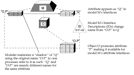
Key Concept—The most common use of model attribute interfaces is to change the name of an attribute as it promotes to the next level. This allows the attribute to appear more familiar or appropriate to the user of the model. This operation is called attribute renaming.
In addition to an attribute’s name, interface descriptions can also apply changes to attribute properties. Each of the properties of an attribute including its default value, numerical range, symbol map, and comments can be modified before being promoted to the model’s interface. It is very common for presentation-related properties such as comments and the symbol map to be changed, because node models are often prepared with specific types of users in mind, and appropriate text may be selected to match the users’ backgrounds.
When property changes are made via the interface descriptions, the new changes must be compliant with specifications set forth by the previous attribute properties. The changes can “specialize” the model further by constraining the choices that the user can make, but they cannot allow the model to violate any of the constraints that existed previously. Therefore, the interface descriptions must not allow a model that would be invalid from the point of view of previous definitions. This rule affects only certain components of properties: numerical ranges, symbol maps, and default values. Constraints are documented in the following table:
Table 31: Constraints on Property Changes in Model Attribute Interfaces
| Property | Constraint |
|---|---|
| Range | If the range property is altered, then it must be included within the previous range. In other words, no value in the new range must lie outside the previous range. See below for possible constraint violations on other properties that may occur as a result of changing the range. |
| Symbol Map | If the previous symbol map does not allow other values, then no symbols with new values may be added. The values in the symbol map must be included in the previously specified range (but not necessarily the new one). In the particular case of attribute merging (see below), the symbols must be included in the new range. |
| Default Value | The default value must be included in the specified range. |
Key Concept—Changes imposed by the attribute interfaces often have to do with altering the properties of the promoted attributes. Common changes involve the attribute’s range, symbol map, and comments. The new property configurations cannot allow violation of the constraints imposed by the previous properties.
Inheritance of Attribute Properties
When configuring an attribute’s properties as part of a model’s attribute interface, each property can be assigned an inheritance status. The inheritance status determines whether the property should be tied to the same property in the definition from which it originates, or whether it can be altered. Because each property maintains its own inheritance status, it is possible to have some properties inherit their configuration from the original attribute definition, and others be altered. Table 35 shows the Node Editor controls that are used to select the inheritance status for certain attribute properties.
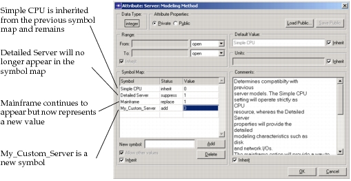
Symbols maps have a slightly more complex behavior than other properties with respect to inheritance of their definition. Rather than require that a symbol map be entirely inherited or redefined, Modeler allows inheritance to be controlled on a per-symbol basis. The Allow other values component of the symbol map also can be inherited or changed. If other values are allowed, then additional symbols can be created and their corresponding values defined. These symbols have a status described as “add”, meaning that they are to be appended to the symbol map. A symbol that is included in the previous definition of the attribute can be removed from the symbol map by using the “suppress” status. If the symbol is to be kept, it can be given the “inherit” status, meaning that it will continue to track its original definition. And finally, the same symbol can be re-used but given a different value by using the “replace” status. The following illustration depicts a symbol map including symbols with each of these status values.
Figure 60: Symbol Status Values
Attribute Merging
Attribute interfaces support another useful mechanism for the transformation of attributes prior to promotion. This mechanism is called attribute merging and allows multiple promoted attributes to be combined into one attribute. While the individual attributes still exist within the context of the model, from the perspective of a model user, one attribute appears. Besides information that may be presented in documentation there is no evidence in Modeler’s user interface that the attribute represents multiple underlying object attributes.
Figure 61: Attribute Merging
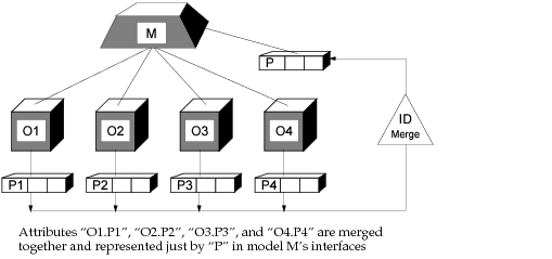
Attribute merging is generally used in situations where a model contains many similar objects and each of them promotes their attributes. For particular real-world applications, it may only make sense to have all of these attributes behave identically under all circumstances. To accomplish this, attribute merging is used to “tie the attributes together”. For example, consider a node model of a switch that contains 16 transmitter and receiver objects, each with their own transmission rate. Now, further assume that for the real world device that this node model represents, different transmission rates are available from the manufacturer, but that in all configurations, all 16 ports always use the same transmission rate. To prevent users from causing these transmission rates to diverge, it would be advisable to merge the attributes into one attribute which could be called “the switch’s transmission rate”. Using attribute merging then provides the important additional benefit of reducing the specification effort required by the user of the model, because only one attribute value need be specified, rather than 16.
The behavior of merged attributes as a set is dependent on the level from which they are accessed. From within the scope of the model, each can be individually modified and examined. Therefore, they may be made to have differing values. From within the context of the model instance, the attributes are unified, and a change to the merged attribute is propagated to all of the individual underlying attributes. However, for the same reason that old attribute names are supported by the Simulation Kernel when attribute renaming occurs, individual attributes with original names are supported for the rename mechanism. Therefore, even though the attributes do not appear on the model instance in the user interface, they can be addressed via the Simulation Kernel’s Ima package APIs. Note that the possibility of diverging underlying values for a merged attribute raises the special case of which value to return when the merged attribute’s value is queried using “op_ima_obj_attr_get()”, or the Simulation Kernel’s debugger, for example. If such a situation occurs, Modeler chooses not to return a value because the merged attribute’s value is ambiguous. Instead, a special code is returned that indicates that diverging values are present. For more information, see “op_ima_obj_attr_get()”.
Key Concept—A model’s attribute interfaces can collapse a group of attributes at the local level into one attribute seen by the model’s users. The attributes are said to be merged. This mechanism is useful when many objects promote the same attribute and it is known that all of these are logically “tied together” (that is, they must always have the same value).
As an attribute promotes through a model’s interface and is inherited by a model instance, the attribute can be placed into one of several states. This state is referred to as the attribute’s status and offers an important control mechanism to the model developer. The status values and their effects are listed in the following table.
Table 32: Attribute Status Values
| Status | Description |
|---|---|
| promoted | The promoted attribute appears at the next modeling level and is initially promoted there as well. |
| set | The promoted attribute appears at the next modeling level with a specified initial value. It does not promote beyond the next level, unless action is taken to explicitly promote it there. |
| hidden | The promoted attribute exists at the next modeling level, but does not appear. A specified initial value is assigned to the attribute and cannot be changed at the next modeling level (no access is possible in the user interface). Because the attribute exists at the next level, it can be accessed during simulation. This mechanism is useful to reduce long lists of attributes when their values can be known in advance, or if their values are not relevant. |
Key Concept—When an attribute promotes through a model‘s interfaces to an instance of the model, the interfaces select one of three possible status settings, determining whether: 1) the attribute appears promoted on the object; 2) the attribute appears with a particular initial assignment; 3) the attribute receives an assignment but doesn’t appear.
Attribute property changes apply not only to promoted object attributes, but also to selected built-in attributes of model instances. For example, the “altitude” attribute of a node object can be controlled using the attribute interfaces of a node model. A user may want to constrain the altitude of the node to be above a certain height for example, in which case the range properties of the attribute would be edited.
Like promoted attributes, the built-in instance attributes can be given a status. This capability is often used to hide unimportant attributes of the instances, to simplify the objects’ attribute lists. In general, this is a good practice because attribute lists can become unnecessarily long and confusing for the model user. Of course, attributes that are relevant, but must have a particular value for correct operation of the model, can be assigned and hidden to ensure no changes by the model user.
Key Concept—Model attribute interfaces also provide control over certain built-in attributes of objects that depend on the model. Like promoted attributes, the supported built-in object attributes can be promoted, pre-assigned, or hidden. This is an important mechanism, if the model’s correct operation relies on specific settings for these attributes.
Supported Object Types
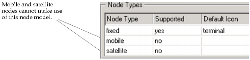
Several types of models (including node, link, and path models) can be used to instantiate more than one type of object. For example, if the Wireless module is used, a node model can be applied to a fixed, mobile, or satellite node. Similarly simplex point-to-point, duplex point-to-point, bus, and tap link objects all make use of link models. Because certain models make sense only for particular types of objects, Modeler provides the ability for certain types of models to distinguish between supported and unsupported object types. This allows Modeler to permit only correct instantiation of the model. Depending on the model type, additional information related to the supported objects can be specified via the same mechanism. In the particular case of node, link and path models, icons used to represent the objects in graphical network models are designated for each supported object type. These icons appear in the editor’s object palette as well as in the network diagrams.
The following figure shows a dialog box section used to specify supported node object types for a node model.
Figure 62: Supported Node Type Specification
Model Keywords
At the time when models are instantiated, Modeler editors must offer the user a choice of the model that is to be used. In particular, the Project Editor makes use of an object palette to present available node and link models. Each model is represented by an icon, as described under Supported Object Types. Users “drag” the icons from the palette to create a new object which is an instance of the corresponding model.
The models that are represented in the object palette are stored in the host computer’s file system and Modeler can be configured to search particular directories for models. Nevertheless, the list of link and node models present in these directories may be extremely long and probably contains many models that are not relevant to the work at hand. Unfortunately, this can cause the object palette to become large and cluttered. Consequently, it may become difficult for users to locate models of interest. To solve this problem, and in general to facilitate searches for models, Modeler provides a model keyword mechanism for certain types of models.
Currently for node, link and path models only, Modeler allows a list of keywords to be specified. Any number of keywords are permitted and each acts independently. In the Project Editor, the object palette can be made to “filter” the model set against a list of desired keywords. In this way, the palette can be made to present only those node and link models that are relevant to the current project.
The reserved keyword “hidden” is used to indicate to Modeler that the model should not be shown, even if other keywords match criteria specified by the user. Only if the keyword “hidden” is explicitly specified will the model be presented. This mechanism is useful when it is decided in advance that a model should rarely be shown due to the low likelihood that users would be interested in it. It is particularly useful in conjunction with the capability called “Model Derivation”, described in Derived Models.
Model Comments
The model attribute interfaces incorporate comments that can be used to provide users with general documentation about the model. Model comments consist of general unstructured text, allowing the model developer to specify information in an arbitrary format. The comments have no functional role and can be left blank if desired, but is a very good practice to document the model’s interfaces in a complete manner. This allows users to make use of the model properly and to understand its functionality without having to view the model internals. If the intended users work with other Riverbed analysis software products, they generally cannot gain access to the model internals and model comments or other supplied documentation are their only resource for understanding the model and how to use it.
Key Concept—Models can incorporate keywords to identify their characteristics or the types of applications for which they are relevant. Modeler can make use of the keywords to selectively present only those models that are of interest. Model comments allow developers to provide users with general documentation of model functionality.