Communication Links
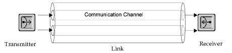
Links allow communication of information between nodes in the form of structured messages called packets. When a packet is submitted to a transmitter in a source node, the packet is conveyed over a link to a receiver in a destination node. A transmitter may support multiple outgoing channels into a link and, similarly, a receiver may support multiple incoming channels from a link. A link is actually composed of one or more communication channels, each of which defines a connection between a transmitter channel and a receiver channel. A communication channel can be thought of as a pipe, where packets are placed in one end by a transmitter channel and retrieved at the other end by a receiver channel. If a link has multiple communication channels, it can be thought of as a “bundle” of pipes, each one conveying packets from the source node to the destination node.
Figure 182: A Link Is Composed of One or More Independent Communication Channels
Modeler supports two types of links: point-to-point and bus (the Wireless functionality adds radio links, as described in Chapter 2 “Modeling Wireless Networks” on page 3. Each link type provides a fundamentally different type of connectivity: point-to-point links connect one source node to one destination node, whereas bus links connect a fixed set of nodes to each other. Each type of link is described in more detail later in this section.
Point-to-point links, bus links, and bus taps are represented as objects in the Project Editor. These links are described by an underlying link model or derived link model in the same way that nodes are described by a node model. For more information on link models, see Chapter 9 “Communication Mechanisms” on page 331.
While the general type of connectivity provided by these links is predefined by Modeler, an open architecture is provided to allow developers to specify customized behavior for each individual link and on a per-transmission basis. This architecture is referred to as the transceiver pipeline because it provides a conduit connecting a transmitter to one or more receivers. The basic functionality of a transceiver pipeline is to determine when a packet arrives at the receiver and if it is successfully received.
The transceiver pipeline has a similar structure for each of the supported link types. In each case, the Simulation Kernel manages the transfer of packets by implementing a series of computations. The sequence of the computations and their interface are standardized for each type of link. However, each computation is performed outside the Simulation Kernel by a user-supplied procedure, called a pipeline stage. This way, Modeler provides an open and modular architecture for implementing link behavior. See Chapter 9 “Communication Mechanisms” on page 331 for more information about transceiver pipelines.
Simplex and Duplex Point-to-Point Links
A point-to-point link can be thought of as a bundle of one or more communication channels between the transmitter(s) and receiver(s) that it connects. Within a point-to-point link, the number of communication channels is static, because there is one communication channel between each transmitter channel and receiver channel of the same index. Packets sent by transmitter channel in the source node will be received by the receiver channel with same index in the destination node. Each communication channel acts independently of the others in the same link, as though it were defined in a separate and parallel point-to-point link.
A simplex point-to-point link defines a connection from a transmitter in the source node to a receiver in the destination node. Packets are conveyed in that one direction. A duplex point-to-point link, however, defines a pair of connections between two nodes, connecting a transmitter in each node to a receiver in the other. Packets can flow in both directions, from each node to the other.
For a point-to-point link to be operable, it must be attached to point-to-point transmitters and receivers in the nodes that it connects. The transmitter and receiver of a simplex point-to-point link are designated using its “transmitter” and “receiver” object attributes. For duplex links, four attributes (“transmitter a”, “receiver a”, “transmitter b”, and “receiver b”) serve to identify the modules within the nodes to which the link is attached.
The point-to-point transceiver pipeline models four link effects: transmission delay, propagation delay, bit errors and error correction. These effects determine when the packet arrives at the receiver and if it is successfully received. The following descriptions of the link behavior is based on the default transceiver pipeline. If the default pipeline procedures require modification to model the effects in a different manner, see “Communication Mechanisms” on page 331 for the details of each pipeline stage.
A packet completely arrives at a receiver after both the transmission and propagation delays have elapsed. The transmission delay is based on the “data rate” attribute of the transmitter channel and the size of the packet. Because each transmitter channel specifies its own data rate, a point-to-point link can support multiple communication channels with different data rates or capacities. The propagation delay is obtained by the transceiver pipeline from the link’s “delay” attribute. This value applies to every communication channel within the link. The default value is 0.0 seconds, but may be set as required to model the propagation delay across a link.
After a packet traverses a link, the transceiver pipeline computes the number of bit errors that occurred and whether they exceed the receiver’s ability to correct them. The number of bit errors allocated to a packet is based on the “ber” attribute of the link and the size of the packet. The default pipeline stage for bit error allocation uses a probabilistic algorithm to compute the number of bit errors. For details, see “Pipeline Stages/Bus Link” on page 6. The number of bit errors that the receiver can correct is determined by the size of the packet and the receiver’s “ecc threshold” attribute, which specifies the maximum number of errors per bit that can be corrected. For example, if a packet’s size is 1000 bits and the error correction threshold value is 0.002, then the receiver can correct the errors in the packet if the number of bit errors is 2 or less. If there are no errors or the receiver is able to correct those that occurred, the receiver accepts the packet and forwards it to the next module in the node. If there are too many bit errors, the receiver drops the packet and does not forward it to the next module in the node.
Bus Links and Taps
A bus link is a constrained broadcast communication medium and therefore connects a limited set of nodes to one another. For those bus transmitters and receivers that are connected to the bus, shared communication channels exist, connecting transmitter channels to the receiver channels with the same index. In the bus link, a shared communication channel has one or more transmitter channels sending packets into it and one or more receiver channels receiving packets from it.
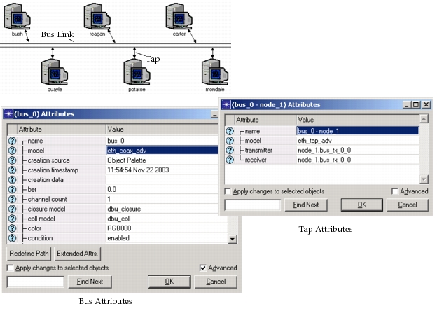
Nodes that require access to and from a bus must contain bus transmitters and receivers and are attached to the bus via another network object called a tap. Taps are simple structural elements used to connect fixed nodes to bus links. A tap has a “transmitter” attribute and a “receiver” attribute that designate the transceivers within the node that are connected to the bus link via that tap.
Most taps have both the “transmitter” and “receiver” attributes set to a non-empty value, allowing packets to travel in both directions between the bus and node. However, it is possible to leave either of these attributes empty (the value NONE can be assigned) to create a unidirectional tap. If only the receiver name is assigned, the tap is referred to as receive-only. If only the transmitter name is assigned, the tap is called transmit-only. Receive-only taps are sometimes used to monitor the status of the bus link to learn about the activities of other nodes, or to collect statistics. Transmit-only taps can be used, for example, by a controller node that periodically emits a synchronization signal and has no need to receive information from other nodes.
Figure 183: Bus Link and Taps with Attributes
Packets are transmitted one at a time from a transmitter channel onto the bus link and may propagate simultaneously in both directions. When a packet is transmitted, each of the eligible receivers is sent a distinct copy of the packet. This allows each receiver to make an independent determination with regard to the correct reception of the packet. In addition, if the packets are received correctly by multiple receivers, then the distinct copies can be operated upon (e.g., modified, destroyed, resent) without affecting each other.
The calculations required to determine when and if a packet is successfully received are performed by the bus link’s transceiver pipeline. The bus transceiver pipeline models five link effects: transmission delay, propagation delay, collisions, bit errors and error correction. The following descriptions of the link behavior is based on the default pipeline procedures. If the default pipeline procedures require modification to model the effects in a different manner, see Chapter 9 “Communication Mechanisms” on page 331 for details on each pipeline stage.
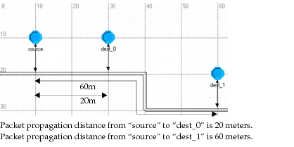
The time that a bit requires to travel from the transmitter to the receiver is the propagation delay. This delay is determined by the bus link’s “delay” attribute and the distance the packet travels from transmitter to receiver. The “delay” attribute specifies the propagation delay in units of seconds per meter, rather than just a fixed value, as in point-to-point links. The distance from a transmitter to a receiver is actually the distance from the transmitter’s tap to the receiver’s, because the taps identify where the transceivers are located on the bus. The distance is not the line-of-sight distance, but the distance along the bus. Because the transmitter may be sending copies of the packet to multiple receivers at different locations, the packets may arrive staggered in time at each receiver.
Figure 184: Packet Propagation Delay Is Dependent upon Distance Along Bus Link
The transmission delay is the time required by the transmitter channel to send a packet. This delay is based on the “data rate” attribute of the transmitter channel and the size of the packet. The last bit of a packet will arrive one transmission delay after the first bit. This delay is important because the Simulation Kernel uses it to determine when a receiver channel is busy and when the entire packet has arrived at the receiver channel.
Because a bus is a shared broadcast medium, two or more transmitter channels may send packets whose arrivals overlap in time at a particular receiver channel. This is known as a collision. When a collision occurs, the transceiver pipeline increments a collision counter that is stored in the OPC_TDA_BU_NUM_COLLS Transmission Data Attribute of each packet involved. See Chapter 9 “Communication Mechanisms” on page 331 for more information on each transmission data attribute built into the packet structure.
After a packet is received at a bus receiver channel, the transceiver pipeline computes the number of bit errors that occurred in the packet. The number of bit errors allocated to a packet is based on the “ber” attribute of the link and the size of the packet. The default pipeline stage for bit error allocation uses a probabilistic algorithm to compute the number of bit errors. For details, see “Pipeline Stages/Bus Link” on page 6.
The bus receiver will accept the packet if there were no collisions during reception and if it can correct any bit errors that may have occurred in the packet. The number of bit errors that the receiver can correct is determined by the size of the packet and the receiver’s “ecc threshold” attribute, which specifies the maximum number of errors per bit that can be corrected. For example, if a packet’s size is 1000 bits and the error correction threshold value is 0.002, then the receiver can correct the errors in the packet if the number of bit errors is 2 or less. If there are no collisions and errors, or the receiver is able to correct those errors that occurred, the receiver accepts the packet and forwards it to the next module in the node. If there is at least one collision or too many bit errors, the receiver drops the packet and does not forward it to the next module in the node.
Because bus links allow one packet transmission to automatically propagate to multiple destinations, they are generally used to represent local area networks, computer buses, or other broadcast-based networks. In addition, because packet broadcasting can be constrained to a subset of the nodes attached to the bus, and even to one destination, bus links can be used to represent networks with a high degree of connectivity or with a dynamic connectivity that would otherwise be difficult to represent using point-to-point links.
Link Consistency
Modeler supports a notion of compatibility for interconnected nodes and links in the Project Editor. The purpose of incorporating this concept in Modeler is to assist the network-level user in constructing correct models. This is particularly important for users who work exclusively at the network level, as do users of other Riverbed analysis software products, because they do not have visibility into the node models to make their own determinations about compatibility issues. These types of users are only aware of the information that is published by node and link model developers in the model comments.
Modeler refers to compatibility of combinations of links and nodes as link consistency. A determination of consistency for a particular grouping of objects is based on criteria applied to certain attributes of these objects. Two types of connections can be subjected to a test for link consistency: the interconnection of a point-to-point link (simplex or duplex) and two nodes on either end of it, and the interconnection of a node and a bus links via a tap. Note that links may actually be connected to a subnetwork object that contains a node, but the connection is still with the node object and the subnetwork’s characteristics are not considered.
The objects that are actually involved in the consistency determination are the link, and the attached transmitter and receiver objects within the nodes. The characteristics of the channel objects which are embedded in the transmitters and receivers that are considered as well. The attributes that are considered for these objects are “data rate” and the “packet formats”. The “data rate” specifies the speed at which information can be transmitted through the object and is given in bits per second. Compatibility is clearly dependent on this attribute because it would not make sense for a device to transmit data at one speed to a device that is only capable of receiving data at a different speed. The “packet formats” attribute specifies the types of packets that the object is capable of carrying. Though in the real world, this is not necessarily a constraint that is imposed by physical objects such as channels and links, it does provide a valuable mechanism for enforcing correct interconnection. Specifically, the channels are viewed as ports of the node and the node model developer has knowledge of the type of communication protocol that is expected to make use of the port. By specifying the same type of information for each port of each node, node model developers provide Modeler with enough knowledge to detect if ports are connected that support incompatible protocols.
Figure 185: Objects Involved in Link Consistency Determination
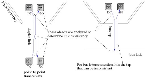
The link consistency criteria are intrinsic to Modeler and cannot be modified by the user. They can be expressed as a series of rules, none of which can be violated if consistency is to be achieved. Because links have only one “packet formats” attribute and one “data rate” attribute, these are compared only against the attributes of the zeroth channel for each transmitter and receiver. Channels with higher indices do not factor into the consistency calculation. These rules are presented in the following table.
Table 95: Link Consistency Rules
| Rule | Details |
|---|---|
| Completeness | All of the transmitters and receivers required by the link must be assigned to a valid object within the nodes on each end. For a simplex point-to-point link, this means that the “transmitter” and “receiver” attributes of the link must be assigned. For a duplex point-to-point link, the “transmitter a”, “receiver a”, “transmitter b”, and “receiver b” attributes must be assigned. Bus link attachments allow transmit-only and listen-only configurations. Therefore it is consistent for a bus tap to have either the transmitter, the receiver, or both assigned. |
| Same number of channels | The “channel count” attribute for the link object and the count of the “channel” compound attribute for each assigned transmitter and receiver must be equal. A promoted value is considered to match any value to which it is compared. |
| Equal data rates | The “data rate” attribute of the link, and the “data rate” attribute of channel [0] of each assigned transmitter and receiver must be equal. A value of “unspecified” may be provided for a “data rate” attribute, in which case, it is considered to match any value to which it is compared. Similarly, a promoted data rate also matches any value to which it is compared. |
| Packet Format Match | The list of packet formats specified in the “packet formats” attribute of the link and the “packet formats” attribute of channel [0] of each assigned transmitter and receiver must have a non-empty intersection. These attributes support the special status values “all formatted” and “unformatted”, both of which can be simultaneously supported. “Unformatted” means that packets with no format are supported. “All formatted” means that any formatted packet can be supported. |
Link consistency plays two primary roles. Its primary use is as a verification mechanism to be used during specification. The Project Editor supports this with the Verity Links operation. This operation detects inconsistent links and indicates them with a red “X” to call attention to them. Double-clicking on the “X” opens a dialog box that describes why the link is inconsistent. Optionally, this operation can attempt to correct the problematic link definitions. See “Project Editor” on page 89 for more information on using the Verify Links operation.
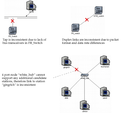
Some examples of inconsistent links are presented below to illustrate the application of the rules in above table. The cross superimposed on each link indicates that it is in an inconsistent state.
Figure 186: Link Inconsistency Examples
The second application of link consistency criteria occurs during simulation. First, the Simulation Kernel attempts to achieve link consistency wherever attributes have been left in the “unspecified” state. Unspecified attributes are made to match the values of the same attributes in other objects, if those are specified. In other words, an unspecified attribute mimics the values of other specified attributes that are considered in the same link attachment. If all of the attributes involved have value of “unspecified”, then the default value for the attribute of the link object is assigned to each of the attributes (note: in the special case where this value is itself unspecified, an error message is issued and the simulation is stopped). After this is done, all attributes values have been resolved and link consistency evaluation can be performed.
If a link is detected to be inconsistent at the start of simulation, the Kernel considers the link to be disabled for the entire simulation. The link object does appear to be present, when queried through the debugger, for example. However, any packets that are submitted to the link’s transmitter are dropped rather than being transmitted. A warning message is generated when this occurs, but the simulation is allowed to continue.
Even though a link might be consistent in terms of its physical attachments, Modeler can still detect inconsistencies between the link and the traffic that it carries. Specifically, a packet might be submitted for transmission whose format is not included in the link’s “packet formats” attribute. The packet format also might not be supported by the transmitter channel in the source node or by the receiver channel in the destination node.
When a packet is detected to be inconsistent with a transmitter channel, the packet is dropped from the transmitter. It does not consume any of the transmitter’s bandwidth, and the transmitter is allowed to move on immediately to begin processing of the next packet that is queued for transmission (if any). This is true of all three types of transmitters. Furthermore, if the packet’s format is inconsistent with the supported formats of the connected link object, point-to-point and bus transmitters discard the incompatible packet in the same manner.
When a packet is received by any of the three types of receivers, the Simulation Kernel verifies that the packet can be supported by the receiver channel, as specified in the channel’s “packet formats” attribute. If the packet format is supported, the packet is forwarded normally to one of the other modules that is attached to the receiver. If the format is not supported, the packet is instead automatically discarded by the Simulation Kernel. Packet format inconsistency at the receiver does not affect any of the pipeline computations which are performed prior to consistency evaluation.
Transceiver Choosing
Note that the Project Editor does not indicate inconsistent links until it is explicitly requested to do so via the Verify Links operation. This brings up the question of when links become inconsistent and when it makes sense to apply this operation. There are several ways in which this can happen, as listed in the following table.
Table 96: Causes of Inconsistency
| Cause | Details |
|---|---|
| Inconsistent at creation | When a link and one or more devices are connected together in the Project Editor, it may not be possible for a consistent link to be established. This may be due to the fact that there are no matching transmitters/receivers available in the node models, or that none are available (i.e., they are already used for other links). Rather than create a link that does not match its transceivers, the Project Editor will simply leave the transceivers unassigned. The link is then inconsistent according to the completeness rule in the table above. |
| External Specification | Network models can also be specified using the External Model Access (EMA) capability. In this case, link transceiver attributes can be configured in an arbitrary manner, and may violate one or more of the rules in the table above. |
| Model changes | A consistent link may become inconsistent due to changes to link or node models. Specifically, removal or renaming of transceiver objects, as well as changes to “data rate”, “packet formats”, and “channel count” attributes may violate one or more of the consistency rules described in the table above. |
Another interesting question is “how do links become consistent?”. In other words, what steps must be taken by the user to form consistent links. The general answer is that the user must ensure that the link consistency rules stated in the table above are all satisfied for the link of interest and the objects attached to it. However, it is a tedious task to manually assign the transceiver attributes of each link to ensure consistency. Fortunately, the Project Editor can help automate this process by automatically selecting the transceiver assignments when a link and a node are attached. This occurs when links are first created in the Editor, and can also be performed retroactively to “repair” inconsistent links. This service is available via the Reselect Transceivers option of the Verify Links operation. See “Verify Links” on page 266 for a description of this procedure.
For certain nodes where all transceivers are similar and would match an attached link, any choice is fine, and the Project Editor can choose the first available transceiver(s). However, it is common for nodes to support several different types of interconnections and therefore contain transceivers with different configurations. In these cases, the Project Editor must attempt to make an intelligent choice. It does so by examining the available transceivers and selecting those that will permit a consistent link to be formed. Transceivers that are already “used” for an existing link are considered unavailable. In general, the editor will attempt to create consistent links whenever possible, taking into account all of the available transceivers in each of the involved nodes. However, if no matching transceivers can be found, the link will still be created and certain transceiver attributes of the link may be left blank.
In selecting transceivers for duplex point-to-point links and bus taps, the editor takes into account logical associations that exist between transmitters and receivers so that they can be kept together. The editor will not break associations between transmitters and receivers, even if there is no other way to form a consistent link. In other words, if an associated transmitter and receiver cannot be simultaneously assigned to the link, then they cannot be used at all.
Link Connectivity
The link connectivity utility allows you to identify the IP interfaces and physical port numbers connected on either sides of a link. The difference in the information provided by this feature and that available using the port information feature is that link connectivity provides information only for the selected link, whereas port information provides a table for all connections on the loaded subnet view.
When link connectivity is enabled, a new operation called Link Interfaces appears when the Attributes dialog box is opened for a given link. The supported link types include duplex/simplex point-to-point links and bus taps.
Procedure 6: Choosing Ports for a Link
-
Open a network model for which interface and port information are required.
-
Right-click on a link.
Result: The Attributes dialog box appears.
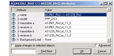
-
Right-click on the link again and select Edit Ports.
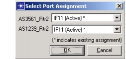
Result: Connected interface and port information for the nodes attached to the link are generated and displayed in the Select Port Assignment dialog box.