Utility Objects
Objects that do not correspond to actual physical infrastructure are also used to construct network models. In general, these do a logical function in the network, such as configuration of network resources on a global level (for example, provisioning of permanent virtual circuits, or PVCs).
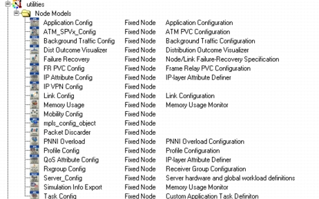
Another typical role for a utility object is to enable a simulation-specific function, such as reporting on use of memory resources. Finally, utility objects can be used to script special events in the simulation, such as the failure of a particular network element at a given time. In all of these cases, utility objects are selected from the palette and deployed into the network model, and in general their location does not matter. They have attributes that control their function in the simulation. To see the utility nodes available, open the Object Palette and expand “utilities,” as shown.
Figure 30: Utilities Object Palette
Failure-Recovery Utility
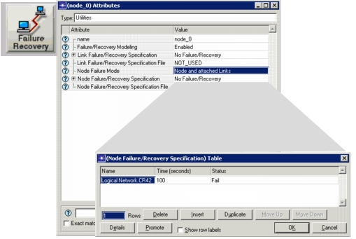
The Failure-Recovery utility object is one that is commonly used to introduce node or link failures at specific times. You can cause the same nodes/links to then become operational (recover) at later times. The example below shows how to configure node failures to have a particular device be disabled for 60 seconds, one hour into the simulation.
Figure 31: Failure-Recovery Utility Object Supports Scripting of Node and Link Failures
The Failure/Recovery configuration utility lets you specify node failures and recoveries in a text file, just as you can for link failures and recoveries. To specify node failures using a text file, specify the filename in the Node Failure/Recover Specification File attribute on the Failure/Recovery utility object.
A file used to specify node failures must adhere to the following format:
<node_name> <action> <time>
In the format above
<node_name>is the name of the node. Both local (to the Failure/Recovery utility subnet) and hierarchical node names are supported. Precedence is given to the local names.<action>can have a value of Failure or Recover<time>is the time for failure or recovery in seconds
Elements in each line must be separated by a tab.
Failure/recovery specification files should end with the following extension:
- Node failure/recovery files: -nfr.gdf
- Link failure/recovery files: -lfr.gdf
Note: Link failure/recovery files no longer need to start with <project>-<scenario> and can now be used across multiple projects and scenarios. To update files that were used to specify link failures in previous releases, you need only add the -lfr.gdf extension to the filename.
Application Utility
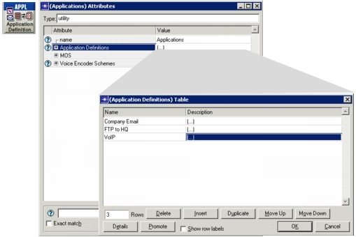
The Application Definition utility node lets you specify general network applications in your model and simulate the traffic each application creates. As shown, you can configure multiple applications and levels of that application’s traffic in the utility node. For detailed information about standard or custom applications in the network model, see “Using Standard Application Models” on page 4.
Figure 32: Application Utility Node
ATM SPVx Utility
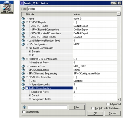
Use the ATM SPVx utility node to specify certain global characteristics to be used on the SPVx traffic demands in a scenario:
- Traffic Characteristics – Defines profiles to be used by different connections (SPVX/PVX/SVC) to characterize their behavior. For example, multiple PVCs between the same source-destination pair can carry different types of traffic (e.g., Email, FTP, HTTP).
- SPVX Start Time Jitter – Specifies a start time jitter and spread for all SPVx traffic demands in the scenario.
Figure 33: ATM SPVx Utility Node
Background Traffic Utility
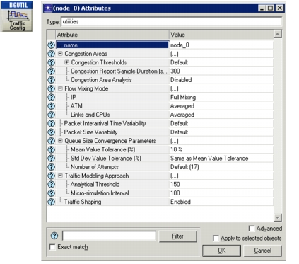
The Background Traffic utility node is one way to add background traffic. Background traffic is analytically modeled traffic that affects the performance of explicit traffic by introducing additional delays. Unlike explicit traffic, background traffic can affect not only discrete event simulations, but also flow analyses. Because each packet that produces traffic on the network is not explicitly modeled, using background traffic can speed up simulations considerably.
Figure 34: Background Traffic Utility Node
Distribution Outcome Visualizer Utility
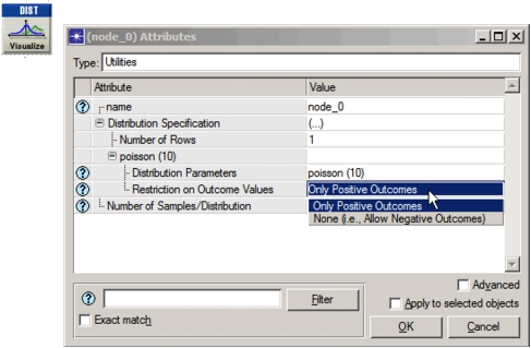
This utility node provides visualizations of outcomes for built-in or scripted distributions. To see a distribution, configure the utility node for the desired distribution, as shown below. Then, select the Distribution Outcomes statistic and run a simulation.
Figure 35: Distribution Outcome Visualizer Utility Node
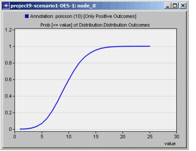
After the simulation, view results for the Distribution Outcomes statistic.
Figure 36: Sample Distribution Outcome
Frame Relay PVC Config Utility
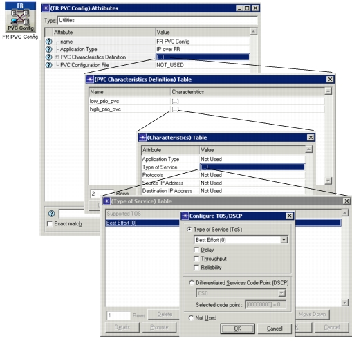
The FR PVC Config object represents a Frame Relay node used to specify PVC configurations. PVCs can either be defined at the interface, read from a .gdf file, or read from an MS-Excel spreadsheet saved as a .csv file. As shown below, you can set global characteristics for all PVCs in a model using the “PVC Characteristics Definition” compound attribute.
Figure 37: Frame Relay PVC Utility Node
IP Attribute Utility
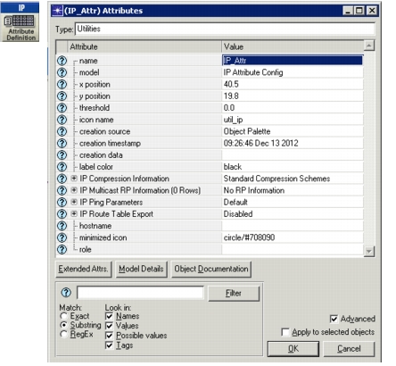
The IP Attribute utility node defines attribute configuration details for protocols supported at the IP layer. These specifications can be referenced by the individual nodes, using symbolic names (i.e., character strings).
Figure 38: IP Attribute Utility Node
You can use the compound attributes described below to further refine protocol behavior.
- IP Ping Parameters – Defines the ping patterns that individual hosts or routers in the network can use to determine connectivity to a specified destination. The patterns you define here can be used to set the ping pattern in the ip_ping_traffic demand model. For an example of how to use these ping patterns, see the “IP” example network icmp_route print scenario. Examine the attributes for the ip_ping_traffic demand.
- IP Compression Information – Specifies the details of various compression schemes used in the network. An IP interface can use any one of the compression schemes defined here. These compression schemes can be set on hosts in the IP > IP Host Parameters > Interface Information > Compression Information attribute. On routers, set the IP > IP Routing Parameters > Interface Information > Compression Information or IP > IP Routing Parameters > Aggregate Interfaces > Compression Information to any of the values defined here.
- IP Multicast RP Information – Specifies the RP (Rendezvous Point) globally for a multicast group address. Alternatively, you may specify RPs locally in the attribute IP Multicasting > PIM Parameters > Processes > Global > Static RP Configuration.
Link Config Utility
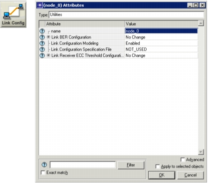
The Link Config object lets you specify time-varying Bit Error Rates (BER) on wired point-to-point and bus links for discrete event simulations. The Link Config object provides you with two ways to specify the BER:
- In table form, using the Link BER Configuration attributes
- From a text file, using the Link Configuration Specification File attribute
Figure 39: Link Config Utility Node
Text files must be in a tab-separated format and must end with an -lcs.gdf extension. Each line in the Link Configuration Specification File consists of a link name, the name of a link attribute to be changed, the new attribute value, and the time the change is to be applied. Link names must match the link names in the network, and time values must be greater than zero. Note that the only attribute value currently supported is BER.
Format for lines in the link configuration specification file:
<link_name> <attribute> <value> <time>
Note that when changing link BER values, you may also need to change the error correction threshold (ECC) on the link’s endpoints. This can also be done using attributes on the Link Config object.
Memory Usage Utility
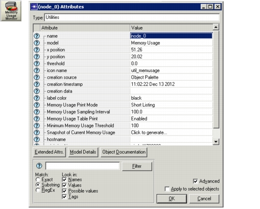
The Memory Usage utility node prints memory usage statistics at specified intervals during simulation execution or a snapshot, when requested. The output includes statistics on static and dynamic simulation objects (the term “simulation object” refers to a broader set than just model objects, and includes internal Simulation Kernel data structures).
Note: The displayed results are similar to the output of the “memstats” command executed in the OPNET Simulation Debugger (ODB). See the ODB Reference Guide for more information.
Figure 40: Memory Usage Utility Node
When this utility is used within simulations, a table is printed:
- at the beginning of simulation before any model initialization takes place,
- after all the models have initialized,
- at the end of simulation, and
- at regular intervals specified using the “sampling interval”.
There are two formats of the table: short and long. The statistics displayed for each format are indicated in the table below.
Table 20: Statistics Shown in Memory Usage Table
| Statistics Displayed | Appears in Short Format | Appears in Long Format |
|---|---|---|
| Size of the object (in bytes) | ✓ | ✓ |
| Number of objects | ✓ | ✓ |
| Number of objects allocated | ✓ | |
| Number of objects deallocated | ✓ | |
| Number of objects in use | ✓ | ✓ |
| Number of objects on free list | ✓ | ✓ |
| Number of objects in reserve | ✓ | |
| Amount of memory used by the object (in kb) | ✓ | ✓ |
| Total simulation object memory usage (in kb) Includes: - General – A shared pool of memory not associated with specific objects. - Other – Denotes memory not classified under any of the printed categories. |
✓ | ✓ |
Profile Config Utility
The Profile Config node, which is related to the configuration of custom applications, has attributes that let you configure timing, repeatability, and sequencing. These attributes are related, so changing one attribute impacts the others. Together the attributes determine the traffic pattern that is generated during the simulation. For a thorough explanation of how to configure this utility node, see “Understanding Timing, Repeatability, and Sequencing” on page 48.
Figure 41: Profile Config Utility Node
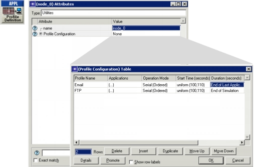
For more information about custom applications, see “Custom Application” on page 34.
Rxgroup Config Utility
The Rxgroup Config utility node specifies the set of possible receivers with which a node can communicate, based on the following criteria:
- Channel match
- Distance threshold
- Pathloss threshold
Figure 42: Rxgroup Config Utility Node
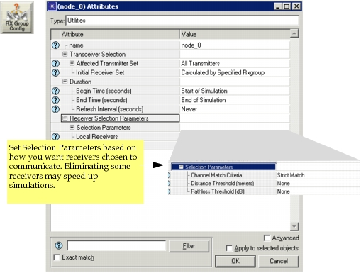
All possible receivers that have a channel match with the transmitter, and fall within the distance and pathloss thresholds, are allowed to communicate. Because some receivers are eliminated through this process, simulations may be faster. The possible simulation time savings are affected by (a) the number of neighbors for a given transmitter in relation to the number of receivers and (b) the refresh interval of the simulation.
Note: Do not use Rxgroup Config in a network model in which any other node affects dynamic receiver group calculation, as conflicts may be encountered in allowed receiver lists.
Simulation Info Export Utility
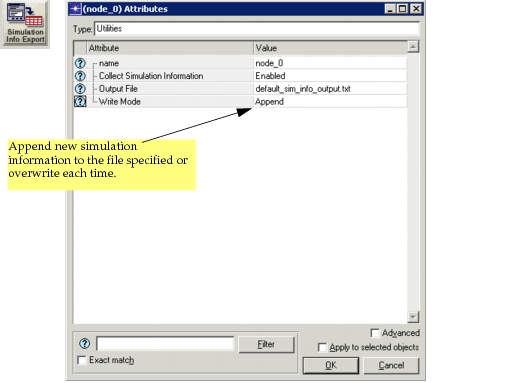
The Simulation Info Export utility node allows you to specify an output file in which to write simulation information. You can choose to append new information to the file for each simulation, or you can choose to overwrite the file each time, as shown.
Figure 43: Simulation Info Export Utility Node
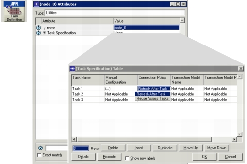
Task Config Utility
Custom applications are configured using two global objects: the Application Utility object and the Task Config object. Tasks function as the building blocks of the custom application and are defined in the Task Config object. Once the tasks have been defined, they are used to build (define) the custom application in the Application Config object. Once defined, the custom application can be used in the profiles that are deployed to the individual workstations or LANs using the application. For more information on this object, see “Custom Application” on page 34.
Figure 44: Task Config Utility