Objects Menu Operations
This section contains descriptions and procedures for using the operations available from the Objects menu in the Node Editor:
- Create
<module> - Create Logical Tx/Rx Association
- Create Packet Stream
- Create Statistic Wire
- Open Annotation Palette
- Show Module Connectivity
Figure 187: Objects Menu (Node Editor)
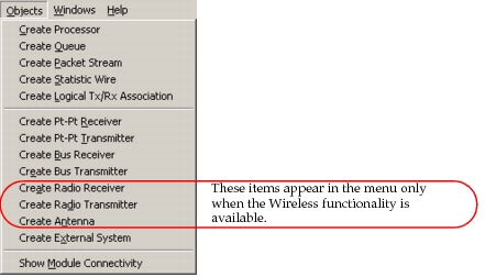
Create <module>
Each module creation operation allows you to create one or more new modules of the selected type within the node model. A module is a functional block that has:
- Inputs (packet streams and statistic wires)
- Outputs (packet streams and statistic wires)
- State memory
- Internal processes. Internal processes provide the logic to determine the module’s outputs, based on the applied inputs and state memory.
-
For processor and queue modules, the internal logic is provided by a process model—either one from the library or one designed by the user in the Process Editor.
-
For an external system (or esys) module, the internal logic is provided by an ESD model (specified in the External System Definition Editor), a process model (designed in the Process Editor), and an external simulation program.
-
All other types of modules are managed in a pre-defined way by the Simulation Kernel. The behavior of these modules can only be controlled by their attributes.
For more information about each module type and its capabilities, see “Node Domain” on page 263.
For more information about external systems, see “External System Domain” on page 325.
For more information about process models, see “Process Domain” on page 165.
-
Each type of module is characterized by a set of attributes that specify its behavior. Attributes are assigned default values by the Node Editor when the module is created. After a module is created, its attributes can be modified using the Edit Object Attributes operation.
Create Logical Tx/Rx Association
This operation creates an association between a transmitter module and a receiver module in a node model. The transmitter and receiver module must correspond to the same link type. That is, a bus transmitter can only be associated with a bus receiver, and a point-to-point transmitter can only be associated with a point-to-point receiver.
The purpose of creating an association between transmitters and receivers is to tightly couple them to attach them to links. Frequently, a node model might make assumptions that the packet streams going to and from transmitters and receivers, respectively, are connected to the same link at the network level. However, because the Project Editor automatically chooses transmitters and receivers when attaching links to nodes, and because there can be multiple transmitters and receivers of each type in a node, it is possible that an attachment will be made that separates a transmitter and a receiver that belong together. The logical association between a transmitter and a receiver indicates to the Project Editor that it should treat the two modules as a unit and attach them to the same link.
While it is possible for users to override transmitter and receiver assignments for links, users of other Riverbed solutions cannot. (These solutions have no visibility into node models and their users are not aware of particular transmitters and receivers). Therefore, the logical transmitter/receiver association is particularly important to ensure that links will be correctly attached to nodes when node models are used in other solutions.
Logical associations are shown by a dashed line segment (or series of segments) connecting the two modules. The line has an arrow at both ends. Only point-to-point and bus transmitters support logical associations, and they must be paired with receivers of the same type. An error message displays if the selected source or destination module is not valid.
Multi-Segment Logical Tx/Rx Associations
It is possible to draw logical associations with more than one line segment. The presence of additional line segments does not affect the node model behavior in any way.
Procedure 204: Drawing a Multi-Segment Logical Association
-
Click on the transmitter module.
-
Move the cursor to a chosen location within the Node Editor—a location not covering a module—and left-click.
Result: This creates a vertex in the multi-segmented logical association.
-
Continue left-clicking at each desired vertex.
Result: A “rubber band” line extends from the last vertex to the current location of the pointer.
-
Left-click on the receiver module to complete the logical association.
Create Packet Stream
This operation creates packet streams between modules in the Node Editor. A packet stream carries packets (arbitrarily-sized collections of data) from the output of a source module to the input of a destination module. It is depicted by a solid line segment (or a series of segments) connecting the icons of two modules. An arrow at the end of a packet stream indicates the direction of data flow.
A given packet stream can carry data in only one direction. Therefore, if two modules are to send messages back and forth, at least two packet streams must be created. It is not always possible to create a packet stream between two modules for the following reasons:
- Some types of modules can only be sources for packet streams, while others can only be destinations. The Node Editor will not allow you to originate/terminate a packet stream at a module that cannot serve as a source/destination.
- Some types of modules can only serve to originate or terminate exactly one packet stream.
The following table lists the support provided by each type of module for packet stream connections.
Table 96: Support for Packet Stream Connections by Module Type
| Module Type | Source or Destination | # of input streams | # of output streams |
|---|---|---|---|
| Processor | Both | User-defined | User-defined |
| Queue | Both | User-defined | User-defined |
| Pt-Pt Receiver | Source | None | User-defined |
| Pt-Pt Transmitter | Destination | User-defined | None |
| Bus Receiver | Source | None | User-defined |
| Bus Transmitter | Destination | User-defined | None |
| Esys | Both | User-defined | User-defined |
Assigning Source and Destination Streams
Source and destination stream index values are automatically assigned when a packet stream is created. Source and destination stream numbers are typically not re-assigned afterwards. However, they appear as the “src stream” and “dest stream” attributes of the packet stream object and can be modified if necessary. When editing these attributes, the Node Editor only allows selection of source and destination streams that have not yet been used.
Multi-Segment Packet Streams
It is possible to draw packet streams with more than one line segment. The presence of additional line segments does not affect the stream’s operation in any way.
Procedure 205: Drawing a Multi-Segment Stream
-
Click on the source module.
-
Move the cursor to a chosen location within the Node Editor—a location not covering a module—and left-click.
Result: This creates a vertex in the multi-segmented packet stream.
-
Continue left-clicking at each desired vertex.
Result: A “rubber band” line extends from the last vertex to the current location of the pointer.
-
Left-click on the destination module to complete the packet stream.
Error: Invalid initial point selected
This error message appears when an invalid module was selected to act as the source of the packet stream. The module might not be capable of supporting any outgoing streams, or might already be attached to the maximum number of outgoing packet streams that it can support.
Error: Invalid intermediate point
This error message appears when an invalid module was selected to act as the destination of the packet stream. The module might not be capable of supporting any incoming streams, or might already be attached to the maximum number of incoming packet streams that it can support.
Create Statistic Wire
This operation creates statistic wires between source modules and destination modules in a node model.
A statistic wire conveys information about the source module to the destination module; the information is the value of a single varying numerical quantity. This quantity, or statistic, can represent a metric of the source module. It can also be a discrete set of flags (representing the state of the source module) that is shared as part of a signaling protocol with the destination module. The statistic is “wired” from the source module to the destination module to make the statistic available for monitoring by the destination module, and possibly to trigger a response in that module.
Statistic wires can communicate values to the destination modules in a “silent” mode, wherein the destination module can simply read the statistic when it needs knowledge of its most current value. Or, statistic wires can be configured to generate a special type of interrupt (a statistic interrupt) at the destination module, in response to particular types of changes in the statistic. For instance, a statistic wire can generate an interrupt for the destination module when its statistic exceeds a specified threshold. See “Node Domain” on page 263 for more information about statistic wires and statistic interrupts.
Statistic wires are graphically depicted by a dashed line segment (or series of segments) connecting the two modules. An arrow at the end of a statistic wire indicates the direction of information flow.
Each type of module has its own unique set of built-in statistics; in addition, user-defined statistics are supported by processors and queues. Built-in statistics are automatically updated by the Simulation Kernel as the state of the source module changes. In the case of processor or queue modules, the process model executing within the module can modify the values of user-defined output statistics by calling the Kernel Procedure op_stat_write().
Any kind of module can be the source of a statistic wire. However, only processor modules and queue modules can be the destinations for a statistic wire. The user-defined processes associated with a processor or queue can use the interrupts and values provided by the statistic wire to adjust their behavior dynamically.
A single statistic wire can carry only one statistic. Moreover, a given statistic wire can carry statistical information in only one direction. When the wire is created, default statistics are assigned to be carried from the source module. From the same source module, the same statistic can be carried to more than one destination module. However, a separate statistic wire is required for each destination module. Thus, a statistic can fan out from a source module.
Figure 188: Statistic Wires
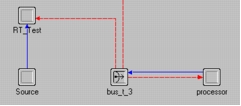
A given destination module (that is, a given queue or processor) can have any number of input statistics. Each input statistic can be assigned to one, and only one, input statistic wire.
For a description of the specific types of statistics available from each module, and for further general information about statistics and statistic wires, see “Node Domain” on page 263.
Statistic Wire Attributes
Each statistic wire is a node model object which possesses attributes that configure its behavior. All attributes can be edited using the Edit Object Attributes operation, which is activated by right-clicking on any part of the statistic wire. This section describes some important statistic wire attributes.
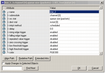
The “submodule” attribute appears only for statistic wires whose sources are transmitters, receivers, or queues. It is, by default, assigned to “channel(0)” for transmitters and receivers, but can be modified to refer to any channel that the source module supports. For queues, the submodule attribute is initially given the value NONE, indicating that the statistic belongs to the queue module as a whole, and not to any particular subqueue. The attribute value can be overridden to specify that a subqueue act as the source of the statistic.
When a statistic wire is created, the Node Editor automatically chooses a value for the “statistic” attribute from the set of available statistics provided by the source module. You can edit the “statistic” attribute to specify a different statistic that you are interested in communicating to the destination module.
Statistic wires are equipped with six types of triggers, which control the interrupt generation associated with changes in the statistic during simulation. Each trigger is represented by an attribute, as shown in the statistic wire attribute dialog box shown below. Each trigger specifies whether a particular type of change in the statistic should generate an interrupt for the destination module. If the value of the trigger is set to “disabled”, then the corresponding change in the statistic does not result in an interrupt. Similarly, if the value is enabled for any of the triggers corresponding to the change, then an interrupt is delivered to the destination module. The last two statistic triggers, “high threshold” and “low threshold”, specify interrupt generation when the statistic value exceeds or becomes less than a specified real number.
Figure 189: Statistic Wire Attribute Dialog Box
For more information about statistic wire triggers, see “Node Domain” on page 263.
Multiple-Segment Statistic Wires
You can create multi-segment statistic wires and drag them using the mouse (the end segments change to reflect the new location). The presence of additional line segments does not affect the statistic wire’s operation.
Procedure 206: Drawing a Multi-Segment Statistic Wire
-
Click on the source module.
-
Move the cursor to a chosen location within the Node Editor—a location not covering a module—and left-click.
Result: This creates a vertex (turning point) in the multi-segmented statistic wire.
-
Continue left-clicking at each desired vertex.
Result: A “rubber band” line extends from the last vertex to the current location of the pointer.
-
Left-click on the destination module to complete the statistic wire.
Error: Invalid intermediate point
This error message appears when the selected destination is not valid. Only queues and processors can be the destination modules for statistic wires.
Open Annotation Palette
This operation adds objects to the model that call attention to or label other model elements, as described in “Open Annotation Palette” on page 235.
Show Module Connectivity
This operation (called “Show Connectivity” on the Object pop-up menu) presents a summary of the packet streams and statistic wires entering and exiting a module within the node model. The summary lists both the source and destination modules for each attached packet stream, statistic wire, and logical association. Also, for each packet stream or statistic wire, the summary displays the index of the associated input or output stream, or the name of the associated input and output statistics, respectively.
You cannot use this operation to modify a module’s connections or to edit the information presented. To modify a module’s connectivity with other modules, right-click on the object and edit its attributes.