Interfaces Menu Operations
This section contains descriptions and procedures for using the operations available from the Interfaces menu in the Node Editor. The items that appear on this menu are described below in alphabetical order:
Model Attributes
This operation defines the attributes of a node model. Typically, model attributes represent characteristics of the node as a whole, as opposed to characteristics of specific objects within it. An object’s or model’s attributes can transcend modeling domains so that they appear to be associated with a higher-level object. This is called attribute promotion and the attribute is said to be promoted to the next modeling domain. In the context of this editor, node model attributes are acquired by node objects that are instances of the node model. The attributes appear on the object as soon as it is created at the network level.
When this operation is invoked, a dialog box is presented which supports the definition of attributes. The set of attributes forms a table, with each attribute occupying an individual row. For each attribute, you can specify its name, group, type, units, and default value. Attribute types can be integer, double (real number), string, toggle (boolean), typed file, or compound. See “Modeling Framework” on page 80 for more information about attribute types and their common applications. For a description of attribute groups, see Custom Attribute Organization.
During the simulation, node model attributes are accessed in the same manner as built-in attributes of nodes. If the attributes are not assigned values in the Project Editor (that is, if they are left as promoted values), they become attributes of the simulation model and can be set at simulation run time. See “Modeling Framework” on page 80 for more information about attribute promotion.
Node Interfaces
A node model’s attribute interface is a collection of information that determines how the model’s attributes behave when the model is used either to create a node instance or to derive a new model. In either case, the attribute interfaces specify which attributes of the node are externally visible, how the attributes can be manipulated, and how they are presented. The attributes that are presented on a node object are the result of conscious choices, made by the developer, of the object’s underlying node model. The model developer can exercise the following control over the attributes of the node object:
- Promote attributes – By promoting an attribute, the model makes it available on the object with no assignment. The object’s value appears as “promoted”. This means that the modeler is making no assumptions about what value might be appropriate for the attribute and is deferring this decision to the individual creating the instance of the model. Each separate instance of the model can independently specify its own value of the attribute.
- Pre-Assign Attributes – This is also known as setting attributes at the level of the model. This mechanism is similar to promotion (described above) in that the attribute appears on the object and can be modified there. However, when the object is created, the attribute automatically receives an assignment determined by the model. This is usually done if the model developer can anticipate reasonable values for all uses of the model. The model user need not assign a value to the attribute, but can override its initial value if necessary.
- Hide Attributes – When an attribute is hidden by a model, it is still present on the object, but no longer appears in the object’s attribute list. Its value is set to a specified initial value, as in the case of pre-assignment, described above. However, it can no longer be set on the object itself via the user interface. This is a useful mechanism to “shield” model users from complex or uninteresting attributes that are known to always require a specific value for the model being considered.
- Rename Attributes – A model can rename attributes to simplify or customize their presentation as they appear on the object.
- Change Properties – The properties of an attribute determine aspects of its operation. Some of these include:
- Constraints on its assignments
- Special values (known as symbols) that can simplify or customize the assignment process
- A default value
- Descriptive comments
The mechanisms described above for configuring attributes allow a model to control attributes that originate within its structure, and also to affect certain built-in attributes of the object itself. For example, the “icon” attribute of a fixed node object is usually specified using the pre-assignment mechanism to “suggest” a particular way of representing the object. In fact, this pre-assignment also determines the icon that represents the model in the Project Editor’s object palette. Because pre-assignment is used, you can still override the selected icon for each object in the Project Editor.
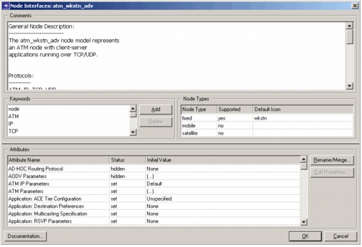
This operation uses a complex dialog box to support configuration of attributes as well as several other aspects of the node model’s interface. The dialog box, appears below followed by a description of these additional model interfaces:
Figure 183: Node Interfaces Dialog Box
-
Renaming and Merging of Attributes – The renaming mechanism accessible through this operation allows you to assign a new name to an attribute. The merging mechanism allows you to replace a group of similar attributes with a single attribute that represents them. Both of these mechanisms are useful to simplify the attribute interface offered by a node model.
Renaming of attributes is typically done to avoid complex attribute names, particularly names that contain the name of a module or another node internal object as a prefix. Users of the model at the network level typically have no interest in the objects that sourced attributes, only in the attributes’ relevance to the behavior of the node. For instance, a node that is an ATM switch might have a module called atm_sw_fabric with a user-defined attribute called “processing rate”. Left promoted, but unmodified, this attribute would appear on a node object at the network level as “atm_sw_fabric.processing rate”. However, to a user of the node model who knows this is an ATM switch, but is unaware of its internal structure, it is probably more meaningful to represent the attribute as “Switch Speed” or another similarly intuitive and appropriate name.
Merging of node model attributes is useful to reduce the number of attributes that a node object inherits from its node model. This mechanism is appropriate in particular cases where it is known that a set of attributes function in an identical manner and are essentially “tied together.” A common example of this occurs when a node contains many pairs of transmitters and receivers which form “ports” of the nodes, to which links can attach. If the “data rate” attributes of the transmitter and receiver channel objects are promoted to allow flexible assignment of this value at the network level, then many such attributes appear on the node object. However, if it is known that all of these “data rate” attributes must be configured to have the same value (i.e., all ports have the same “speed”), then merging them into a single attribute not only reduces the specification effort on each instance of the model, but also enforces the consistency across all ports. This section presents an example detailing the steps necessary to merge data rate attributes for multiple transceiver objects in a node model.
-
Model Keyword Declaration – The keywords of a node model allow it to be selectively displayed in the Project Editor object palette. A model can declare any number of keywords that represent characteristics that it has. These keywords are compared to those requested when configuring the object palette to determine whether to offer the model as a choice. The objective of this mechanism is to allow the user to reduce the number of models presented in the object palette, while presenting only those models that are of interest for the current application.
For more information about model keywords, see “Project Editor” on page 89.
-
Model Comment Specification – Each model contains a set of comments that describe its characteristics, potential applications, and any information that might be of interest to a user of the model. Because not all users have access to node model internals, the comments can provide the primary available information about the model’s capabilities and interfaces. Embedding documentation on the model’s interfaces, as an intrinsic part of the model itself, provides convenient access to information for model users, and helps to ensure that model documentation remains consistent with a model as it evolves through different phases of development.
-
Node Documentation – This operation lets you associate two kinds of documentation with the node model:
- help card – an Adobe Acrobat documentation file located in one of your mod_dirs directories. The dialog box includes a pull-down list of available help cards.
- tooltip – a text string that appears when the cursor rests on an instance of the node in the Project Editor.
-
Node Type Support – A node model supports one or more types. The possible types are fixed, mobile, and satellite (mobile and satellite nodes require the Wireless functionality). To specify which subset of these three types is supported, choose Node Interfaces from the Interfaces menu. It is possible to support one, two, or all three types of nodes for a given node model. When the model is displayed in the Project Editor object palette, one icon appears for each model type that it supports.
Procedure 202: Creating and Merging Data Rate Attributes
-
In the Node Editor, create several receiver modules, as follows:
1.1 Click the Create Pt-Pt Receiver toolbar button. 1.2 Click in the tool area several times, creating receiver modules. 1.3 Right-click to end the operation.
-
Select all receiver modules by drawing a selection box around them.
-
Promote the data rate for the receivers, as follows:
3.1 Right-click on one of the receivers to display the Attributes dialog box. 3.2 Click on the Apply Changes to Selected Objects checkbox to select it. 3.3 Click on the Value of the “channel” attribute to display the Compound Attribute Table dialog box. 3.4 Promote the “data rate” by left-clicking on the value, then clicking on the Promote button. 3.5 Click OK to close the channel dialog box. 3.6 Click OK to close the Attributes dialog box.
-
Merge the data rate attributes, as follows:
4.1 Choose Node Interfaces from the Interfaces menu. 4.2 Click the Rename/Merge Attributes button. 4.3 Type “data_rate” in the Auto fill Promotion Name field. 4.4 Move all the data rate attributes in the Unmodified Attributes column to the Modified Attributes column (for example: “:pr_0.channel [0].data rate”). 4.5 Click OK to close the dialog box. 4.6 Notice that there is now only one data rate attribute in the Edit Node Model dialog box; it is named “data_rate” and its status is “promoted”.
-
Click OK to close the Edit Node Model dialog box.
Node Statistics
This operation promotes selected module statistics to the node level. When you click on the Original Name field, a pop-up menu displays all the statistics available for all modules in the node model. By default, the Promotion Name for a statistic is the same as the original name, but you can edit the Promotion Name to be shorter or more meaningful. You can also enter customized comments for this statistic. When the statistic appears in the Probe Editor as an available statistic for a node, the Promotion Name and Comments you specify here are presented.
Self Description
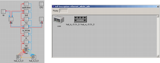
This operation allows you to set the information about a node that is used to match node models to the nodes in an imported topology. The self description (see Self Description Components) specifies information such as what type of machine the node represents (such as a workstation or hub), how many ports it has, and what interfaces the ports support (see Ports).
Figure 184: ethernet_wkstn_adv Model and Self Description Dialog Box
Self Description Components
A self description has three basic parts:
-
Priority – During topology import, if more than one node model matches an imported node, the model with the highest priority is used.
-
Requirements – These specify the node model characteristics that are used to match against the characteristics of nodes in an imported topology. Each characteristic has a value and a comparator. The comparator specifies what relationship must exist between the values of a characteristic for the node model and a node in the imported topology for a match to occur, as listed in the following table.
Table 95: Requirements Comparators
Comparator Meaning Equals The imported node’s value must equal that of the node model. One-of The imported node’s value must equal one of the values listed for the node model. Range The imported node’s value must be in the range (numeric or alphanumeric) specified for the node model. Contains The imported node’s value must contain that of the node model. -
Assignments – These specify attributes that are assigned to the node model when it is chosen to represent an imported node.
Ports
A node model self description should include information about all ports supported by the node. Each transmitter–receiver pair must be described, although multiple ports can be described by one port icon if they have the same description and have consecutive port numbers.
Procedure 203: Creating a Node Self Description
-
Choose Interfaces > Self Description.
Result: The Self Description dialog box opens. New models (without a self description) have only a Core icon. Models that already have a self description also have one or more Port icons.
-
Set the priority for the node.
-
Describe the core model:
3.1 Right-click the Core icon to open the Core Self Description dialog box.
**Figure 185: Core Self Description Dialog Box** 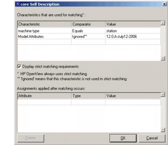3.2 Specify any requirements and assignments for the node model. 3.3 Click OK to close the Core Self Description dialog box.
-
Describe the ports:
4.1 If necessary, click the Add Port button to create a Port icon. 4.2 Right-click on the Port icon to open the Port Self Description dialog box.
**Figure 186: Port Self Description Dialog Box** 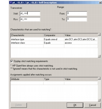4.3 Enter the names of a transmitter–receiver pair. To specify multiple transmitter–receiver pairs with consecutive port numbers, use “
<n>” instead of a port number in the name (for example,hub_tx_<n>_0) and enter the minimum and maximum port numbers in the Range fields. 4.4 Specify any requirements and assignments for the node model. Port assignment attribute names can contain the “<n>” wildcard described in the preceding step. 4.5 Click OK to close the Port Self Description dialog box. -
Click OK to close the Self Description dialog box.