Bus Transceiver Pipeline
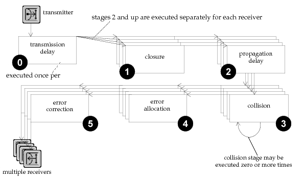
Because a bus link is a broadcast medium, each transmission can potentially affect multiple receivers attached to the bus. In addition, when processing a transmission, a bus link may exhibit different behavior and timing with respect to each receiver. As a result, a separate pipeline must be executed for each receiver attached to the bus.
The bus transceiver pipeline consists of six stages, most of which must be executed on a per-receiver basis whenever a transmission occurs. However, the first stage (transmission delay) is used to compute a result that is common to all destinations, and therefore may be executed just once. In addition, each individual pipeline sequence may or may not fully complete, depending on the result of the second stage (closure), because this stage is responsible for determining if communication between the transmitter and receiver is possible. Finally, the fourth stage (collision) may be executed multiple times for each transmitted packet, because it is possible for a packet to be involved in more than one collision. The structure of the bus transceiver pipeline is depicted in the following diagram.
Figure 232: Bus Link Transceiver Pipeline Execution Sequence for one Transmission
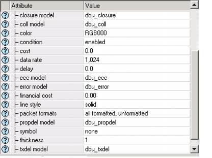
The pipeline stages for a particular bus link can be specified using the appropriate attributes of the bus link object, as shown below.
Figure 233: Bus Link Attributes for Specifying Pipeline Stages
Reserved Transmission Data Attributes
The Simulation Kernel sets aside a number of TDAs to provide pipeline stages with access to a minimum standard set of values, and to support communication between itself and the pipeline stages as well as between the stages and each other. The TDAs reserved for these purposes in packets transmitted over bus links are defined below. For compactness, the symbolic constants that represent the TDA’s indices are shown in a short form without their common prefix. When actually used, each symbolic constant appears with the character sequence “OPC_TDA_BU_” prepended to the names given below. The datatype of each TDA is identified in the table next to the symbolic constant name: “D” represents a double-precision floating-point attribute, and “I” represents an integer attribute.
Table 111: Bus Pipeline Reserved TDAs
| Symbolic Constant | Definition | Assigned By | Modifiable by Stages |
|---|---|---|---|
TX_OBJID (I) |
object ID of bus transmitter | Kernel | no |
LINK_OBJID (I) |
object ID of bus link | Kernel | no |
TX_TAP_OBJID (I) |
object ID of transmitter’s tap | Kernel | no |
TX_CH_OBJID (I) |
object ID of tx channel | Kernel | no |
CH_INDEX (I) |
index of tx and rx channel | Kernel | no |
RX_OBJID (I) |
object ID of bus receiver | Kernel | no |
RX_TAP_OBJID (I) |
object ID of receiver’s tap | Kernel | no |
DISTANCE (D) |
distance between rx and tx (in meters) | Kernel | no |
NUM_COLLS (I) |
number of collisions experienced by packet to date | Kernel, stage 3 | yes |
END_RX (D) |
time when reception will complete | Kernel | no |
CLOSURE (I) |
capability of tx to reach rx | stage 1 | yes |
TX_DELAY (D) |
time required to complete transmission on tx side | stage 0 | yes |
PROP_DELAY (D) |
time required for packet’s signal to travel from tx to rx | stage 2 | yes |
NUM_ERRORS (I) |
number of bit errors affecting packet | stage 4 | yes |
PK_ACCEPT (I) |
decision to accept/reject packet | stage 5 | yes |
ND_FAIL (D) |
earliest simulation time at which node failure occurred during reception of packet | Kernel (if failure occurs) | no |
ND_RECOV (D) |
latest simulation time at which node recovery occurred during reception of packet | Kernel (if recovery occurs) | no |
Stage 0: Transmission Delay
The transmission delay stage is the first stage of the pipeline, and is specified by the “txdel model” attribute of the bus link. It is invoked immediately upon beginning transmission of a packet. This is the only stage for which one execution is performed to support all pipelines that result from a new transmission (i.e., the computation is shared by all resulting pipelines).
This stage is invoked to calculate the amount of time required for the entire packet to complete transmission. This result is the simulation time difference between the beginning of transmission of the first bit and the end of transmission of the last bit of the packet. The Simulation Kernel uses the result provided by this stage to schedule an end-of-transmission event for the transmitter channel that is used to send the packet. When this event occurs, the transmitter may begin transmission of the next packet in the channel’s internal queue, if any are present; otherwise the transmitter channel becomes idle. In addition, the transmission delay result is used in conjunction with the result of the propagation delay stage to compute the time at which the packet completes reception at the link’s destination (i.e., the time at which the last bit finishes arriving is the time at which it finishes transmitting added to the propagation delay on the link).
The Simulation Kernel requires that the transmission delay stage procedure accept a packet address as its sole argument. The computed transmission delay is then expected by the Kernel within the TDA represented by the symbolic constant OPC_TDA_BU_TX_DELAY. The assigned value should be a nonnegative double-precision floating-point number. No other results are required. Syntax requirements for this stage are specified in Figure 234.
Figure 234: Templates for Bus Pipeline: Transmission Delay Stage
Sequential simulations:
void
tx_delay_template (Packet* pk)
	{
	double			result;

	FIN (tx_delay_template (Packet* pk))

	/* extract required information from packet. */

	/* perform calculation of transmission delay. */

	/* place result in TDA to return to Simulation Kernel. */
	op_td_set_dbl (pk, OPC_TDA_BU_TX_DELAY, result);

	FOUT
	}
Parallel simulations:
void
tx_delay_template_mt (OP_SIM_CONTEXT_ARG_OPT_COMMA Packet* pk)
	{
	double			result;

	FIN_MT (tx_delay_template (Packet* pk))

	/* extract required information from packet. */

	/* perform calculation of transmission delay. */

	/* place result in TDA to return to Simulation Kernel. */
	op_td_set_dbl (pk, OPC_TDA_BU_TX_DELAY, result);

	FOUT
	}
Stage 1: Closure
The closure stage is the second stage of the pipeline, and is specified by the “closure model” attribute of the bus link. It is invoked once for each receiver attached to the bus. These invocations take place immediately after the return of the transmission delay stage, with no simulation time elapsing in between. The purpose of this stage is to determine whether a particular receiver is capable of receiving a transmission. The ability to receive a transmission is referred to as closure between the transmitter and the receiver, hence the name of the stage.
The Simulation Kernel expects an integer value to be provided by this stage. The Kernel uses this result to determine whether to execute the remainder of the bus pipeline for the particular receiver in question. If the integer value is equal to the symbolic constant OPC_TRUE then closure is established and communication between the transmitter and receiver is possible; otherwise the value OPC_FALSE should be used to indicate that communication is not possible.
The Simulation Kernel requires that the closure stage procedure accept a packet address as its sole argument. The closure indication is then expected by the Kernel within the TDA represented by the symbolic constant OPC_TDA_BU_PROP_CLOSURE. No other results are required. Interface requirements for this stage are specified in Figure 235.
Figure 235: Templates for Bus Pipeline: Closure Stage
Sequential simulations:
void
closure_template (Packet* pk)
	{
	int			result;

	FIN (closure_template (Packet* pk))

	/* extract required information from packet. */

	/* perform calculation of closure indication. */

	/* place result in TDA to return to Simulation Kernel. */
	op_td_set_int (pk, OPC_TDA_BU_CLOSURE, result);

	FOUT
	}
Parallel simulations:
void
closure_template_mt (OP_SIM_CONTEXT_ARG_OPT_COMMA Packet* pk)
	{
	int			result;

	FIN_MT (closure_template (Packet* pk))

	/* extract required information from packet. */

	/* perform calculation of closure indication. */

	/* place result in TDA to return to Simulation Kernel. */
	op_td_set_int (pk, OPC_TDA_BU_CLOSURE, result);

	FOUT
	}
Stage 2: Propagation Delay
The propagation delay stage is the third stage of the pipeline, and is specified by the “propdel model” attribute of the bus link. It is invoked for each receiver that is attached to the bus; this invocation takes place after the return of the closure stage with no simulation time elapsing in between. The purpose of this stage is to calculate the amount of time required for the packet’s signal to travel from the bus transmitter to the bus receiver. This result is generally dependent on factors such as the type of physical medium, the distance between the source and the destination, and the frequency of the signal. Regardless of the factors involved, the Simulation Kernel expects a double-precision floating-point value to be provided by this stage. The Kernel uses this result to schedule a beginning-of-reception event for the receiver channel that the packet is destined for. In addition, the propagation delay result is used in conjunction with the result of the transmission delay stage to compute the time at which the packet completes reception (i.e., the time at which the last bit finishes arriving is the time at which the packet begins transmission added to the sum of the transmission delay and the propagation delay).
The Simulation Kernel requires that the propagation delay stage procedure accept a packet address as its sole argument. The computed propagation delay is then expected by the Kernel within the TDA represented by the symbolic constant OPC_TDA_BU_PROP_DELAY. The assigned value should be a nonnegative double-precision floating-point number. No other results are required. Interface requirements for this stage are specified in Figure 236.
Figure 236: Templates for Bus Transceiver Pipeline: Propagation Delay Stage
Sequential simulations:
void
prop_delay_template (Packet* pk)
	{
	double			result;

	FIN (prop_delay_template (Packet* pk))

	/* extract required information from packet. */

	/* perform calculation of propagation delay. */

	/* place result in TDA to return to Simulation Kernel. */
	op_td_set_dbl (pk, OPC_TDA_BU_PROP_DELAY, result);

	FOUT
	}
Parallel simulations:
void
prop_delay_template_mt (OP_SIM_CONTEXT_ARG_OPT_COMMA Packet* pk)
	{
	double			result;

	FIN_MT (prop_delay_template (Packet* pk))

	/* extract required information from packet. */

	/* perform calculation of propagation delay. */

	/* place result in TDA to return to Simulation Kernel. */
	op_td_set_dbl (pk, OPC_TDA_BU_PROP_DELAY, result);

	FOUT
	}
Stage 3: Collision
The collision stage occupies the fourth position in the bus transceiver pipeline, and is specified by the “coll model” attribute of the bus link. Unlike other pipeline stages, it may be executed multiple times or not at all within a given pipeline sequence. This stage is called each time that the packet of interest experiences a new collision; a collision is considered to occur when the packet of interest initially arrives at the receiver and another packet has already begun arriving on the same channel; or when the packet of interest has already begun arriving and another packet begins. In other words, collisions are symmetric events experienced by both packets involved. When a collision occurs, one call to the collision stage is generated to support both of the packets’ pipelines. Because an arbitrary number of transmissions may occur on the bus during the reception time of a packet, one packet may experience multiple collisions.
The purpose of the collision stage is to provide application-specific models with knowledge of collisions. The Simulation Kernel expects no particular results to be generated by the invoked pipeline procedure. However, the Kernel does reserve a TDA to keep track of the number of collisions experienced by a packet, because this is a typical requirement of most pipelines, including the default stages. This TDA is represented by the symbolic constant OPC_TDA_BU_NUM_COLLS and is initially set to zero when the packet is transmitted. Typically, if a collision is judged to be relevant in the sense that it has a bearing on later processing of the packet, then the logic in this stage increments the value of the TDA OPC_TDA_BU_NUM_COLLS.
The Simulation Kernel requires that the collision stage procedure accept two packet addresses as arguments. The first packet address is that of the earlier arriving packet, and the second address is that of the later arriving packet that triggered the collision. Interface requirements for this stage are specified in Figure 237.
Figure 237: Templates for Bus Transceiver Pipeline: Collision Stage
Sequential simulations:
void
collision_template (Packet* earlier_pk, Packet* later_pk)
	{
	FIN (collision_template (earlier_pk, later_pk))

	/* Test for collision; update TDAs if appropriate */
	op_td_increment_int (earlier_pk, OPC_TDA_BU_NUM_COLLS, 1);
	op_td_increment_int (later_pk, OPC_TDA_BU_NUM_COLLS, 1);

	FOUT
	}
Parallel simulations:
void
collision_template_mt (OP_SIM_CONTEXT_ARG_OPT_COMMA Packet* earlier_pk,
	Packet* later_pk)
	{
	FIN_MT (collision_template (earlier_pk, later_pk))

	/* Test for collision; update TDAs if appropriate */
	op_td_increment_int (earlier_pk, OPC_TDA_BU_NUM_COLLS, 1);
	op_td_increment_int (later_pk, OPC_TDA_BU_NUM_COLLS, 1);

	FOUT
	}
Stage 4: Error Allocation
The error allocation stage is the fifth stage of the pipeline, and is specified by the “error model” attribute of the bus link. It is invoked after the entire packet has completed reception at the destination, to estimate the number of bit errors that occurred. This is referred to as allocating errors to the packet. This result is generally dependent on a bit-error probability which reflects the quality of the link, and the packet length. This calculation usually does not include errors due to collisions.
The Kernel uses the result of this stage to report error statistics for the receiver channel object. In addition, this result is typically used by the final stage of the bus link pipeline to decide whether to accept the packet and subsequently forward it via the receiver channel’s output stream.
The Simulation Kernel requires that the error allocation stage procedure accept a packet address as its sole argument. The computed number of errors affecting the packet is then expected by the Kernel within the TDA represented by the symbolic constant OPC_TDA_BU_NUM_ERRORS. The assigned value should be an integer value between zero and the packet length (inclusive). No other results are required. Interface requirements for this stage are specified in the following figure.
Figure 238: Templates for Bus Pipeline: Error Allocation Stage
Sequential simulations:
void
error_alloc_template (Packet* pk)
	{
	int			result;

	FIN (error_alloc_template (Packet* pk))

	/* extract required information from packet. */

	/* perform estimation of number of errors in packet. */

	/* place result in TDA to return to Simulation Kernel. */
	op_td_set_int (pk, OPC_TDA_BU_NUM_ERRORS, result);

	FOUT
	}
Parallel simulations:
void
error_alloc_template_mt (OP_SIM_CONTEXT_ARG_OPT_COMMA Packet* pk)
	{
	int			result;

	FIN_MT (error_alloc_template (Packet* pk))

	/* extract required information from packet. */

	/* perform estimation of number of errors in packet. */

	/* place result in TDA to return to Simulation Kernel. */
	op_td_set_int (pk, OPC_TDA_BU_NUM_ERRORS, result);

	FOUT
	}
Stage 5: Error Correction
The error correction stage is the sixth and final stage of the pipeline, and is specified by the “ecc model” attribute of the bus link. It is invoked immediately after the return of the error allocation stage, with no simulation time elapsing in between. The purpose of this stage is to determine whether the arriving packet can be accepted and forwarded via the channel’s corresponding output stream to one of the receiver’s neighboring modules in the destination node. This is usually dependent upon whether the packet has experienced collisions, the result computed in the error allocation stage, and the ability of the receiver to correct the errors affecting the packet (hence the name of the stage). Based on the determination of this stage, the Kernel will either destroy the packet, or allow it to proceed into the destination node. In addition, this result affects error and throughput statistics collected for the receiver channel.
The Simulation Kernel requires that the error correction stage procedure accept a packet address as its sole argument. The determination to accept or reject the packet is then expected by the Kernel within the TDA represented by the symbolic constant OPC_TDA_BU_PK_ACCEPT. The assigned value should be an integer equal to the constant OPC_TRUE to indicate acceptance; otherwise the integer value OPC_FALSE should be assigned. No other results are required. Interface requirements for this stage are specified in the following figure.
Figure 239: Templates for Bus Pipeline: Error Correction Stage
Sequential simulations:
void
error_correction_template (Packet* pk)
	{
	int			result;

	FIN (error_correction_template (Packet* pk))

	/* extract required information from packet. */

	/* determine if packet should be accepted or rejected. */

	/* place result in TDA to return to Simulation Kernel. */
	op_td_set_int (pk, OPC_TDA_BU_PK_ACCEPT, result);

	FOUT
	}
Parallel simulations:
void
error_correction_template_mt (OP_SIM_CONTEXT_ARG_OPT_COMMA Packet* pk)
	{
	int			result;

	FIN_MT (error_correction_template (Packet* pk))

	/* extract required information from packet. */

	/* determine if packet should be accepted or rejected. */

	/* place result in TDA to return to Simulation Kernel. */
	op_td_set_int (pk, OPC_TDA_BU_PK_ACCEPT, result);

	FOUT
	}