Transceiver Pipeline Mechanics
The transceiver pipeline has a similar structure for each supported link type. In each case, the Simulation Kernel manages the transfer of packets by implementing a series of computations, each of which models particular aspects of link behavior. The sequence of the computations and their interface are standardized for each type of link. However each computation, referred to as a pipeline stage, is performed outside the Simulation Kernel by a user-supplied procedure, called a pipeline procedure. This way, Modeler provides an open and modular architecture for implementing link behavior.
A link’s underlying implementation can generally be thought of as a sequentially executed set of pipeline stages. The pipeline stage sequence of a link is executed once for each packet transmission that is submitted at the source of the link. In other words, when a packet is sent to a transmitter, the Simulation Kernel proceeds to call appropriate pipeline stages to process the packet. Certain pipeline stages are executed when the packet is transmitted, and others are executed later due to the delay associated with the traversal of the link and transmission of the packet.
The principal objective of a transceiver pipeline is to determine whether a packet can be received at the link’s destination. This determination is usually made in the final stages of the pipeline based on information computed during earlier stages. The primary vehicle used to convey information between the stages is the packet itself, which is provided as an argument to each pipeline procedure. The packet is also used by the pipeline stages to return information to the Simulation Kernel. A link model may also contain local statistics, which can also be used to convey information about a particular link object across different pipeline stages.
To carry both user-defined and standard pipeline information, packets contain a special storage area consisting of an array of values called transmission data attributes. Transmission data attributes (TDAs) are either integer or floating-point numerical values that are assigned to a particular location within the packet. TDA locations are specified by integer index, and the meaning of each location is dependent upon the particular type of link and the conventions agreed-upon by the pipeline stages.
At the time that a packet enters a pipeline (i.e., when it begins transmission), a certain number of TDAs are automatically assigned by the Simulation Kernel to provide information to the pipeline stages concerning the context of the transmission. For example, the object ID of the link, of the transceivers, and of the channel objects, as well as certain relevant attributes of these objects, are generally already present in predefined TDAs of the packet by the time the first stage is executed. The particular set of TDAs that is automatically provided depends upon the type of link, and is documented for each link type.
The predefined TDAs that are set up prior to a pipeline execution are reserved for the exclusive use of the Simulation Kernel. In addition, the Kernel reserves certain standard TDAs for the pipeline stages to communicate certain information to it as well as to each other. For each of these TDAs, the Kernel defines a special symbolic constant to represent the TDA’s integer index. See Chapter 28 “Symbolic Constants” on page 1 of the Discrete Event Simulation API Reference Manual.
In each set of predefined TDAs, a certain number are provided in advance or computed by the Kernel as the pipeline execution proceeds. These TDAs have a fixed meaning and always serve to communicate information from the Kernel to the stages, but not the reverse. As a result, these TDAs may not be used by pipeline stages for alternate purposes (simulation errors will result if this is attempted). However, the TDA array is extensible and allows any positive integer index to be specified when assigning or obtaining an attribute value. Therefore, custom pipeline designs may make use of any higher-numbered TDAs (above the highest predefined TDA) that are not reserved by the Kernel to communicate additional information between stages. Special symbolic constants representing the highest reserved TDA index are provided to support this application. These constants appear in the table below. For a given pipeline, the lowest unreserved TDA index is obtained by adding one to the appropriate constant.
Table 102: Maximum Reserved TDA Indices
| Link Type | Constant Representing Maximum Reserved Index |
|---|---|
| Point-to-Point | OPC_TDA_PT_MAX_INDEX |
| Bus | OPC_TDA_BU_MAX_INDEX |
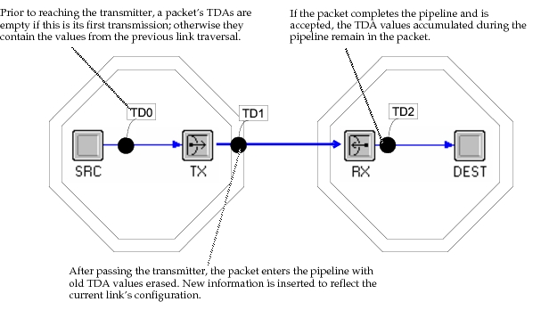
In addition to supporting communication of information between pipeline stages and the Kernel, and between pipeline stages and each other, TDAs can be used to pass information from the pipeline stages to processes in a link’s destination node. The information accumulated in a packet during its traversal of a transceiver pipeline is not stripped when the pipeline’s execution completes. In fact, it remains within the packet until the packet is transmitted again. As a result, any process within the destination node of a link may obtain information generated by pipeline stages that processed the packet as the packet was transferred. This capability may be useful to support implementation of sophisticated decision making within link destination nodes based on conditions in the arriving links. For example, a node receiving packets transmitted by radio may make use of pipeline-generated information about interference to adjust its antenna orientation or its reception frequency.
Note that while processes within nodes can obtain information from TDAs in packets, they are not capable of modifying existing TDAs or extending the TDA array to incorporate new values. Therefore, TDAs cannot be used to communicate information from processes to the pipeline stages (this policy is due to the fact that information inserted into the TDAs would be overwritten anyway at the time of actual transmission). It is possible however to use ordinary packet fields for this purpose, because pipeline stages are capable of accessing these values.
Figure 223: Transformation Phases for a Packet’s Transmission Data Attributes