Packet Transmission Mechanisms
Packets are rarely used as static storage items that simply remain within one physical or logical context. Instead, they are almost always created dynamically to allow information to be transferred between contexts. The Simulation Kernel offers several mechanisms to support packet-based communication. One or more of these mechanisms may be appropriate, depending upon the relationship between the context that initiates the transfer and the context that receives the packet.
Packet Streams
Packet streams are physical connections that support the transfer of packets between modules within the same node. Packet streams are defined between an output port of a source module and an input port of a destination module. These ports are usually referred to as the source module's output stream and the destination module's input stream, respectively.
Each module may have an unlimited number of input streams and an unlimited number of output streams. “Fan-in” and “fan-out” are not allowed; that is, each input stream can be the recipient of only one packet stream object, and each output stream can be the source of only one packet stream object. However, any or all input and output streams may be left unconnected.
Queuing at the Input Stream
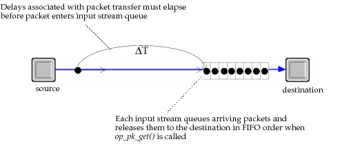
Each packet stream contains one queue for packets; this queue is associated with the destination module's input stream to allow packets to wait until the destination module is ready to acquire them by calling op_pk_get(). The Simulation Kernel does not place a limit on the number of packets a packet stream's queue can hold. The packets are maintained in the order in which they arrive and, because the destination module can only obtain the head of this queue (by calling the KP op_pk_get()), the queue can be considered first-in-first-out (FIFO).
Figure 210: Queuing in Packet Streams
Interrupt Methods
If a packet stream's source module is a processor or a queue, it can send packets that it owns to the packet stream's destination module by calling any of the four variants of the KP op_pk_send(). Each of these KPs implements the transfer with a slightly different behavior, as explained below.
-
op_pk_send(): This form of packet transfer is referred to as standard packet sending, because it is the most commonly used. A call toop_pk_send()results in the scheduling of a stream event for the destination module to indicate the arrival of a new packet; the time of this event is the current time added to the value of the packet stream's “delay” attribute. If the value of this attribute is zero (which is the default), the stream event is scheduled for the current time. Note that module priorities throughout the system, and interrupt priorities at the destination module, affect the execution order of this event relative to others scheduled for the same time.Immediately prior to generating a stream interrupt for one of the processes in the destination module, the Simulation Kernel inserts the transferred packet at the tail of the input stream's queue. If there are no other packets queued at that time, then the destination process may obtain the packet with one call to
op_pk_get(); otherwise, multiple calls to this KP are required to obtain the packet. At its option, the destination process may also choose to ignore the new arrival and leave it in the input stream's queue. Note that if the interrupt cannot be delivered to a destination process, the packet is still queued, allowing it to be obtained at a later time. -
op_pk_send_delayed(): This form is similar to standard packet sending in that it also makes use of event scheduling and generates an interrupt for an appropriate process in the destination module. However, the KPop_pk_send_delayed()supports the specification of a positive delay value that postpones the arrival of the packet at the destination's input stream for an additional amount of time. The stream event representing the arrival of the transferred packet at the destination occurs at the current time added to the sum of the specified delay and the value of the packet stream's “delay” attribute. All other aspects of this form of packet transfer are identical to those obtained by usingop_pk_send().Note: Because
op_pk_send_delayed()allows the delay value to be set independently on each call, the order of packet arrivals at the destination of a given stream may not match the order in which packets are sent using this KP. -
op_pk_send_forced(): This form of packet transfer does not make use of event scheduling. Instead it causes the sending process to be suspended and immediately queues the packet in the input stream and generates an event for the destination module. The packet remains queued regardless of whether the event results in one of the destination module's processes receiving an interrupt. No delays are possible in forced packet transfers, so the packet stream's “delay” attribute is ignored.Note that the sending process resumes execution only after the destination process blocks. For a description of the general behavior of forced events, see Chapter 4 “Modeling Framework” on page 80.
-
op_pk_send_quiet(): This form of packet transfer is used to avoid the generation of an interrupt for any of the destination module's processes. In other words, the only real effect of this KP is to place the transferred packet at the end of the packet stream's queue. The packet is inserted into the queue on an immediate basis (i.e., this action is not scheduled and can be assumed to have completed by the time the KP call returns).op_pk_send_quiet()is most often used in conjunction with an access interrupt to immediately forward a packet in response. The KPop_pk_send_forced()cannot be used in this situation because it would result in a forced event feedback loop between the source and destination modules; this is due to the fact that access interrupts, generated by the KPop_strm_access(), are also forced interrupts.This KP is also sometimes used as a device to reduce the total number of interrupts due to packet transfers. The general technique employed for this purpose is to forward a large number of packets in a row using
op_pk_send_quiet()followed by one packet transfer usingop_pk_send()orop_pk_send_forced(). The process that is interrupted as a result of the last packet transfer then determines the number of packets contained in its input stream(s) by callingop_strm_empty()andop_strm_pksize(). The interrupted process can use this information to decide whether to extract some or all of the transferred packets.
Packet Delivery
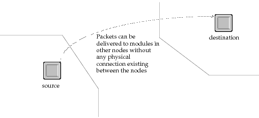
Packet streams support communication only between modules within the same node. If modules use only this means of transferring packets then transmitters and receivers must be relied upon to convey packets between nodes. However, in some cases, it is not convenient to connect all nodes that directly transfer packets to each other. In addition, certain systems in which communicating nodes would rely on intermediate nodes to relay packets may sometimes be accurately and more simply modeled by abstractly allowing direct communications, even though no physical connections exist. To support modeling of such systems, Modeler provides a mechanism referred to as packet delivery, that allows any processor or queue module to directly transfer packets to any other processor or queue module, regardless of physical location.
Figure 211: Packet Delivery Between Modules in Unconnected Nodes
Packet Delivery Mechanics
With respect to the destination side of the mechanism, packet delivery operates similarly to packet sending via streams. In other words, packets are inserted into the queue of an input stream of a destination module, and depending on the selected interrupt method, an event may be generated.
To initiate a packet delivery, a process may call any of the KPs op_pk_deliver(), op_pk_deliver_delayed(), op_pk_deliver_forced(), and op_pk_deliver_quiet(). The desired interrupt method can be specified by using the correct KP. The four delivery KPs have the same behavior as the correspondingly named stream-based KPs described in the previous section.
Because the destination module is not implicitly related to the source module, as in the case of packet streams, it must be explicitly designated when a packet delivery is initiated. The destination module's object ID is therefore expected by each of the KPs that support packet delivery. A number of methods exist for determining the object IDs of destination modules; these methods are supported by the KPs of the Id and Topo packages of the Simulation Kernel.
Similarly, the input stream to which a packet will be delivered must be specified explicitly at the time where the delivery is requested. Input streams are identified by integer index. Packets may be delivered to any input stream, including those that are connected to packet stream objects and those that are not. Note that delivery to an input stream whose index exceeds that of the highest connected input stream causes the allocation of memory for every intermediate index; while the amount of memory per index is small, the total allocation can be large because it grows linearly with the maximum index.
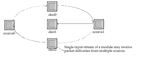
Because packet delivery operations are independent of each other, there are no “fan-in” restrictions for the sources of a particular input stream. In other words, any number of sources may deliver packets to the same input stream. Of course, one source may also deliver packets to multiple input streams.
Figure 212: Fan-In and Fan-Out of Packet Delivery Mechanism
Communication Links
After a packet is created by a module, it can be transferred to another module in the same node; that module can in turn transfer it to a third module in the same node. In many cases however, the packet must ultimately be transmitted to modules in other nodes. The previous section described the use of packet delivery as a means of transferring packets between nodes. Packet delivery is an abstract representation of a physical link which may be useful when the existence of links cannot be known in advance or when actual physical characteristics of the links are not required for simulation accuracy. Modeler also supports a more direct representation of physical links with two types of communication link models referred to as point-to-point and bus (radio links are also available with the Wireless functionality, as described in Chapter 2 “Modeling Wireless Networks” on page 3).
Point-to-Point Links
Point-to-point links allow packets to be transmitted between one pair of nodes. Two types of point-to-point links are provided: simplex point-to-point links, which support the transfer of packets from a transmitter in one node to a receiver in another; and duplex point-to-point links, which connect a transmitter-receiver pair in one node to a transmitter-receiver pair in another. A duplex link acts as two simplex links that run in opposite directions.
Figure 213: Equivalent Duplex and Simplex Point-to-Point Link Configurations

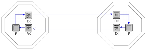
For a point-to-point link to be operable, it must be attached to point-to-point transmitters and receivers in the nodes that it connects. The transmitter(s) and receiver(s) of a simplex point-to-point link are designated using its “transmitter” and “receiver” object attributes; for duplex links, four attributes (“transmitter a”, “receiver a”, “transmitter b”, and “receiver b”) serve to identify the modules within the nodes to which the link is attached. The transceiver modules are important from a modeling point-of-view because they represent the exit and entry points for packets in the transmitting and receiving nodes respectively. In other words, a transmitter module can be viewed as the “gateway” for packets departing to a remote node. To send a packet to a remote node attached by a point-to-point link, a module can simply send the packet the correct point-to-point transmitter module within its own node; the transmitter then provides the service of transporting the packet to the receiver at the other end of the attached point-to-point link.
Figure 214: Transmitters and Receivers Act as Gateways to/from other Nodes
Each point-to-point link can be thought of as a “bundle” representing one or more communication channels between the transmitter(s) and receiver(s) that it connects. The number of channels in a link is determined by the “channel count” attributes of the connected transmitter and receiver objects. Each channel acts independently of the other channels in the same link, as though it were defined in a separate and parallel simplex link. However, the ability to bundle channels together is provided to improve the convenience of defining multichannel trunks.
Point-to-point link channels can be thought of as a pipe between a port of a point-to-point transmitter in a source node and a port of a point-to-point receiver in a destination node. Ports are referenced by numerical index and correspond directly to the input streams and output streams for transmitters and receivers respectively. In other words, a packet can be transmitted using the n-th channel of a link by sending that packet into the n-th input stream of the transmitter at the link's source. At the link's destination, arriving packets are issued by the receiver on its n-th output stream.
The following figure shows the flow of packets.
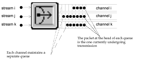
Figure 215: Correspondence between Input Streams, Channels, and Output Streams

Each channel incorporates a simple first-in-first-out queue on its transmitting side. The purpose of the queue is to regulate transmissions in a channel so that the content of only one packet is being transmitted at any given time. Because a packet generally requires a nonzero amount of time to transmit, other packets that arrived later must wait until its transmission has completed before theirs can begin. Because the FIFO queue has no holding capacity limitation, this mechanism allows packets to be forwarded to a transmitter module's input stream at an arbitrary rate, while still respecting the correct timing for individual transmissions.
Figure 216: Built-in Queuing of Transmitter Channels
Both types of point-to-point links can be configured to affect packet transmission in several ways. Underlying each link is a series of user-definable models called pipeline stages. In general, the pipeline stages do computations related to the transmission of a packet to decide the time of reception and whether a packet is received correctly. The complete operation and specification of pipeline stages is described Pipeline Stage Definition. However, in general, pipeline stages can make use of attributes of a link in performing the computations that are required of them. In particular, most pipeline stage implementations use the point-to-point link attributes “ber” and “delay”, which are defined to represent the probability of a bit being received in error and the propagation delay for a signal on the link, respectively. In addition, the “data rate” attribute of a channel object is usually taken into account by one or more of the pipeline stages.
Bus Links
Bus links allow one packet transmission to automatically propagate to multiple destinations. These types of links are generally used to represent local area networks, computer busses, or other broadcast-based networks. In addition, because packet broadcasting can be constrained to a subset of the nodes attached to the bus, and even to one destination, bus links can be used to represent networks with a high degree of connectivity or with a dynamic connectivity that would otherwise be difficult to represent using point-to-point links.
As with point-to-point links, nodes attach to bus links via dedicated transmitter and receiver modules. In this case, bus transmitter and bus receiver modules must be used. Attachments are formed by using a third object, called a tap, to connect the node to the link. A tap has a “transmitter” attribute and a “receiver” attribute that must be used to designate the transceivers within the node.
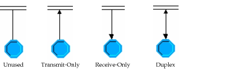
Most taps have both the “transmitter” and “receiver” attributes set to a non-empty value, allowing packets to travel both to and from the bus into the node. However, it is possible to leave either of these attributes empty (the value NONE can actually be assigned) to create a unidirectional tap. If only the receiver name is assigned, the tap is referred to as receive-only; if only the transmitter name is assigned, the tap is called transmit-only. Receive-only taps are sometimes used to monitor the status of the bus link to learn about the activities of other nodes, or to collect results. Transmit-only taps can be used, for example, by a controller node that periodically emits a synchronization signal and has no need to receive information from other nodes.
Depending on whether taps are configured as receive-only, transmit-only, or bidirectional, they are drawn differently in the Network Editor where they are defined. The following diagrams depict the four possible representations (it is possible, though not useful, to have a tap with no transmit or receive capability).
Figure 217: Bus Tap Configurations
A transmitted packet can propagate simultaneously in both directions on a bus link. The physical distances between nodes may be factored into the computation of arrival times at the various receivers. This calculation is generally also based on the “delay” attribute of the bus link, which represents the time in seconds required for the signal to propagate a distance of one meter. Therefore, one packet transmission can result in time-staggered arrivals at the various bus receivers.
In the same way that point-to-point links consist of a bundle of separate channels, bus links can also act as many independent broadcast mediums. The number of channels in a bus link is determined by the “channel count” attributes of the attached bus transmitter and bus receiver modules. When a packet is transmitted on the n-th channel of a bus transmitter, it is received by all bus receivers attached to the bus that have a sufficient channel count (i.e., channel count greater than n, because channel indices begin at zero). Receivers that have an insufficient number of channels are not affected by the transmission. Those receivers that are affected and that receive the packet correctly issue the packet to a neighboring module via their n-th output stream.
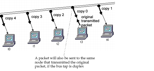
With respect to transmission of packets, bus link channels behave identically to point-to-point link channels. In other words, each channel incorporates an unlimited-capacity queue that can accept packets at any rate, and packets are then transmitted one at a time onto the bus link. When a packet is transmitted, each of the eligible receivers is sent a distinct copy of the packet. This allows each receiver to make an independent determination with regard to the correct reception of the packet. In addition, if the packets are received correctly by multiple receivers, then the distinct copies can be operated upon (e.g., modified, destroyed, resent) without affecting each other.
The following figure shows the packet replication associated with broadcasting on a bus link.
Figure 218: Replication of Transmitted Packet on a Bus Link
Bus links support the notion of a collision which corresponds to the simultaneous presence of two or more arriving packets at the same bus receiver and on the same channel. Because, in general, packets take a nonzero amount of time to transmit and to receive (i.e., time measured from the transmission of the first bit to the transmission of the last bit), a packet can be considered to be “arriving” at a receiver during a finite interval. If another packet begins arriving before the completion of another packet's reception interval, the two packets are considered to have collided. The bus receiver channel remains in a collided state until one of the packets completes its reception interval, leaving only one other packet present.
Because packet collisions take place at the receiver, propagation delays and relative positions of nodes on the bus link can play a role in determining whether they occur. This effect is automatically taken into account by the bus link model, because the arrival of each packet is scheduled based on these parameters and collisions are only determined when packets arrive, not when they are sent.
In general, collisions are considered as destructive events that prevent the correct reception of either packet involved. This is the default behavior provided for the bus link. However, like point-to-point links, the behavior of bus links can be customized by modifying the underlying models or pipeline stages. These can be configured to interpret collisions differently; for example, a collision may be considered to not have a destructive effect if its total duration is less than a defined threshold. The general theory and use of bus link pipeline stages are described in Bus Transceiver Pipeline.
Consistency of Physical Links
Not all links that are placed between nodes are necessarily valid. Modeler considers only certain links to be properly configured and usable for the transfer of packets. A valid point-to-point or bus link is said to be consistent; an invalid point-to-point or bus link is called inconsistent. Inconsistent links do not support packet flow during simulation. To determine consistency of each link, Modeler uses pre-defined criteria that are applied to the link object, and the transceiver objects that are assigned to the link, on each end if applicable. Consistency relates to compatibility of the components that form the connection: these include transmission data rate, supported protocols, and numbers of supported channels. For an in-depth explanation of how link consistency is evaluated, see Chapter 7 “Network Domain” on page 292.
Link Model Definition
Modeler provides several types of links; each type supports a different form of communications between two or more nodes. For those links that are represented as objects (i.e., point-to-point, bus, and bus tap), Modeler uses the notion of a model to better handle large numbers of objects. Link models are specified using the Link Editor. For more information about the Link Editor, see Chapter 8 “Link Editor” on page 508.
As described in Chapter 4 “Modeling Framework” on page 80, a model is a class definition which can be used to create instances that conform to particular specifications. In this case a link object is an instance of a link model. This is the same relationship that exists between nodes and node models. However, unlike a node, a link is not composed of underlying objects. All of the specifications for a link's behavior are contained within a set of attributes. Attributes can specify characteristics such as the link's propagation delay, error rate, and the transceivers that it attaches to, if any. In addition, attributes are used to select a series of underlying C language procedures, called pipeline stages, which implement most of the computations and decisions made by a link. While the pipeline architecture is fixed for each type of link, user-defined pipeline procedures may be inserted into it to achieve customized link behavior (refer to later parts of this section for a description of how the transceiver pipeline works). In other words, a link object's specification is controlled entirely via attributes, and therefore, a link model consists primarily of defining how these attributes should be configured. This is done via a specification mechanism called attribute interfaces, similar to the specification included in a node model. Attribute interfaces are briefly described in a link-specific manner in Link Attribute Interfaces and Derived Link Models.
Link Attribute Interfaces and Derived Link Models
This section describes how link model developers can use a mechanism called model attribute interfaces to exercise control over built-in link attributes, as well as to specify a variety of aspects of a link model's interface presented to the model user. The concepts in this section are described in a more general and complete fashion in Chapter 4 “Modeling Framework” on page 80.
The role of link attribute interfaces is to specify how a link model appears from the point of view of a user who is working with the model in the Network Domain. The attribute interfaces contain several components, the most important of which is called attribute interface descriptions. These are described in the following sub-section; a second sub-section provides a brief explanation of the other components.
Link Attribute Interface Descriptions
As mentioned previously, link models contain no objects. There are therefore no object-promoted attributes that can be passed to the link objects in the Project Domain. The role of attribute interface descriptions is therefore simpler for links than for nodes. In the case of links, the interfaces descriptions apply only to the built-in attributes of link objects. In other words, attributes such as the “delay” or “data rate” of a link can be controlled via this mechanism. Pipeline stage attributes, such as the “txdel model” (transmission delay model) can also be affected. Using the Attribute Interface Descriptions component of the attribute interfaces, the link model developer can apply the following types of changes to the attributes that the link model offers:
Table 97: Control Provided by Link Attribute Interface Descriptions
| Mechanism¹ | Description |
|---|---|
| Attribute Renaming | Provide a new name for an attribute as it is appears from the link model user's point of view. This is the name of the attribute as it is seen on a link object in the Network Domain. |
| Attribute Merging | Replace a set of attributes with one new attribute. The underlying attributes are tied together in the sense that changes to the new attribute are propagated to each of them. |
| Attribute Properties Changes | Certain attribute properties, including range, symbol map, comments, and default value can be altered. |
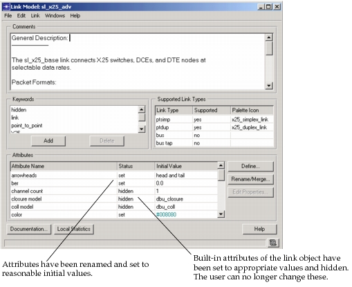
| Attribute Status Changes | An attribute can be given one of three status values: promoted, set, or hidden. Promoted attributes appear on a link object without a value. Set attributes appear on the link object with a value chosen in advance by the link model developer; they can be changed on a per-link basis, however. Hidden attributes have a specified value, but are not visible on the link object, and therefore cannot be changed. |
| Attribute Specification | Modeler allows you to change the default behavior when a user changes a link's attribute settings. You can specify a custom ETS library and event handlers by clicking the ETS Handlers button. |
Note 1: For an in-depth discussion of the mechanisms in this table (except attribute specification), see Chapter 4 “Modeling Framework” on page 80.
Figure 219: Attribute Interface Descriptions for a Link Model
Additional Link Model Interfaces
The Link Model Attribute Interfaces also regroup several other parts of a link's interface, though these are unrelated to attributes. These are listed in the following table.
Table 98: Additional Link Model Interfaces
| Interface | Description |
|---|---|
| Keywords | Each link model can carry a set of keywords that are used to identify its relevance to particular network modeling efforts. Users of the Network Editor can specify keywords of interest to display only those models that are useful to them in the editor's Object Palette. |
| Comments | A textual description of the link model allowing the link model developer to provide any desired information to the model user. Typically information in the comments includes: link model functionality (i.e., what sort of real-world link it represents); factors affecting link consistency; significance of major attributes, etc. |
| Supported Link Type | Specifies whether the model is capable of being used for simplex point-to-point, duplex point-to-point, bus, bus tap, or any combination of these. |
For a detailed description, see Chapter 4 “Modeling Framework” on page 80.
Link Model Derivation
In certain cases, link model developers, or even model users, will find that an existing link model has all of the capabilities that they require, but in addition provides too much flexibility to the model user. While providing extra capability may not seem like a problem, it may in fact be undesirable for a variety of reasons, which are listed in the following table.
Table 99: Reasons to Specialize a Link Model
| Problem | Details |
|---|---|
| Complexity can overwhelm end-user | The more flexible and parameterized a model is, the more complex it is for an end-user to configure. In many cases, the parameters of a general model will not appear familiar to the end-user and the work required to configure it for each instance will exceed the end-user's knowledge. If attribute values can be specified in advance and match the user's requirements, then the link model will be significantly easier to deploy at the network level. |
| Flexibility can permit invalid configurations | The availability of many attributes may provide the opportunity for the user to create a link configured in an invalid manner. |
| End-user expects particular presentation | The end-user of the link model typically expects a particular interface that matches his experience with similar real-world links or other models. If this interface can be realized, the model will be much more “user-friendly”. |
In these problem situations, users are seeking what we can refer to as a specialization of the link model. A specialized version of the link model is less general and flexible, but is tailored to the needs of a particular application, or at least a more specific application than the original model. To create a specialization of a link model, Modeler provides a mechanism called Model Derivation. Model Derivation allows the mechanisms that are available in the Link Model Attribute Interfaces to be applied to an existing link model. The result of this operation is a new, more limited link model, called a derived model that depends on the original model, which is called the parent model.
For more information about model derivation, see Chapter 4 “Modeling Framework” on page 80.