Model Assistant
Model assistant files are ASCII text files used to specify a set of changes to a scenario. You can specify multiple changes in one file and save the file for later use. Model assistant files can be applied to a scenario, invoked during import, or created from within a scenario.
You can create a model assistant file to
- Create subnetworks, nodes, links, and demands
- Set object attributes
- Import node aliases
- Specify static routes
- Specify object locations
- Configure the order and visibility of subnet layers
- Assign roles to network objects
- Reorganize node hierarchically in subnets
With the Model Assistant file, you can perform the following tasks:
-
Editing a Model Assistant File
Although you can edit a model assistant file from the UI, model assistant files may be edited from any text editor and appear as shown in Figure 54. You can more learn about the format of model assistant files by creating one and examining it in ASCII format.
Saving Topology to a Model Assistant File
The following procedure describes how to create a Model Assistant file for a network topology.
Procedure 47: Saving Topology to Model Assistant File
-
Open any scenario in the Project Editor.
-
Choose Topology > Model Assistant > Save Current Topology to File…
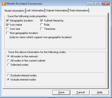
Result: The Model Assistant Conversion dialog box appears.
Figure 48: Model Assistant File Conversion Dialog Box
-
Define the attributes you want to save in the Model Assistant file.
3.1 Specify the node attributes and for which set of nodes in the Node Information tab.
3.2 Specify the link attributes and for which set of links in the Link Information tab.
3.3 Specify the subnet attributes and for which subnets in the Subnet Information tab.
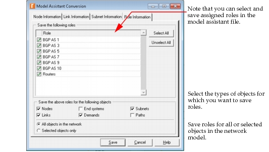
3.4 Specify the roles you want to save in the Role Information tab.
Figure 49: Role Information Tab – Model Assistant File
3.5 Click Save.
-
Provide a filename. The default filename is
<project>-<scenario>-ma_export. -
Click Save.
Editing a Model Assistant File
The following procedure describes how to edit a Model Assistant file using the GUI.
Procedure 48: Editing a Model Assistant File
-
In the Project Editor, choose Topology > Model Assistant > Edit File…
Result: The Edit Model Assistant File dialog box appears.
Figure 50: Model Assistant Dialog Box
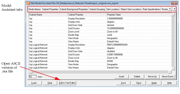
The tabbed sections of the model assistant file are started in order, from left to right, when the model assistant file is applied during import or from the menu.
-
The Model Assistant dialog box shows a series of tabs, listed in Table 19. Each tab corresponds to a different type of information. The tabs are started in order (from left to right) when the model assistant file is applied. Some entries require you to specify attribute names exactly.
- If you do not want to apply a certain type of data, leave the page empty.
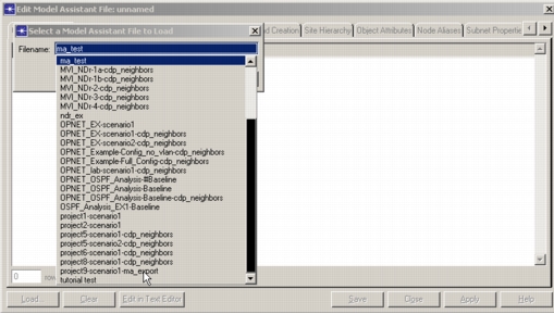
- If you want to load a previously-saved .ma file, click Load and choose the filename. See Figure 53 for an example.
- If you want to reset all settings on all pages and reenter your data, click Clear.
- If you want to save your data to a model assistant file for future use, click Save.
For more information, see Specifying Attributes in the Model Assistant.
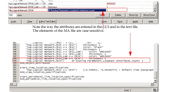
Note: Attributes are case-sensitive. For example, to add a loopback interface on a router, the attribute “IP Routing Parameters.Loopback Interfaces” plus the “count” (number of rows” attribute) must be typed exactly. This would appear as shown in Figure 51 in the text version of the file or in the GUI. If one or more rows already exist, you must enter n + x, where n is the number of existing rows and x is the number of rows you want to add.
Figure 51: Adding an Interface with the Model Assistant File
-
Click Apply to apply your data to the network, or click Close to close the dialog box without applying your data.
Table 19: Model Assistant File Tabs
| Tab | Description |
|---|---|
| Object Destruction | Specify network objects you want to destroy. Each row in the table represents an object to be destroyed. Add rows, then click and select an object name or double-click and type in an object name. |
| Subnet Creation | Specify subnets you want to create in the network. Each row in the table represents a subnet to be created. Enter the name of the subnet you want to create. You must specify a full hierarchy for the subnet; otherwise, the new subnet is placed in the top subnet. For example, a full hierarchy looks like this: top.MidAtlantic.Bethesda.If the specified hierarchy does not exist, the intermediate subnets are created automatically when the model assistant file is applied. |
| Node Creation | Specify nodes you want to create in the network. Each row in the table represents a node to be created, by node name and node model. - You must specify a full hierarchy for the node name; otherwise, the new node is placed in the top subnet. If the specified hierarchy does not exist, the intermediate subnets are created automatically when the model assistant file is applied. For example, a full hierarchy looks like this: top.MidAtlantic.Bethesda.- For node model, you can select a model from the pull-down menu (single-click) or type the model name (double-click) (e.g., ethernet2_slip0_firewall). |
| Link Creation | Specify links you want to create in the network. Each row in the table represents a link to be created. The columns are as follows: - Link Name – Name of the link object. - Source Node – Source node of the link. You do not need to specify the full hierarchical name of this node. If there is only one node with the specified name in the network, the model assistant will find it. - Source Port – Source port of the link. - Destination Node – Destination node of the link. You do not need to specify the full hierarchical name of this node. If there is only one node with the specified name in the network, the model assistant will find it. - Destination Port – Destination port of the link. - Data Rate – Data rate of the link. You can select a data rate from the pull-down menu (single-click) or type the data rate (double-click). - Link Model – Model to use for the link object. |
| Demand Creation | Specify demands you want to create in the network. Each row in the table represents a demand to be created; the columns are as follows. - Demand Name – Name of the demand object. - Source Node – Source node of the new demand. You do not need to specify the full hierarchical name of this node. If there is only one node with the specified name in the network, the model assistant will find it. You can select an existing node or node to be created from the pull-down menu (single-click) or type the node name (double-click). - Destination Node – Destination node of the new demand. You do not need to specify the full hierarchical name of this node. If there is only one node with the specified name in the network, the model assistant will find it. You can select an existing node or node to be created from the pull-down menu (single-click) or type the node name (double-click). - Demand Model – Model name of the demand object. You can select a demand model from the pull-down menu (single-click) or type the model name (double-click). |
| Site Hierarchy | Change the hierarchy of sites in your network. Each row in the table represents a site whose hierarchy is to be changed; the columns are as follows. - Original Site Name – Name of the site whose hierarchy you want to change. You do not need to specify the full hierarchical name of this site; if there is only one site with the specified name in the network, the model assistant will find it. You can select a site from the pull-down menu (single-click) or type the site name (double-click). - New Site Hierarchy – New hierarchy for the site. You can select a subnet from the pull-down menu (single-click) or type the subnet name (double-click). If the specified hierarchy does not exist, the intermediate subnets are created automatically when the model assistant file is applied. |
| Object Attributes | Specify attributes for the various objects in your network. Each row in the table represents an object attribute; the columns are as follows. - Object Name – Name of the object whose attribute you want to set. You can select a network object from the pull-down menu (single-click) or type the object name (double-click). - Attribute Name – Name of the attribute to set. This can be a simple or a compound attribute. Note that simple attributes include simple (non-compound) attributes of compound attributes. - Attribute Value – New value for the specified attribute. If you specified a compound attribute for the name, you can enter only symbolic values. |
| Node Aliases | Specify aliases on the nodes in your network. Each row in the table represents an alias; the columns are as follows. - Node Name – Name of the node whose aliases you want to set. You can select a node from the pull-down menu (single-click) or type the node name (double-click). - Alias – Alias to set on the specified node. |
| Subnet Properties | Set display properties for subnets in your network. Each row in the table represents a property; the columns are as follows. Subnet Name – Name of the subnet whose properties you want to set. You do not need to specify the full hierarchical name of this subnet. You can select a subnet from the pull-down menu (single-click) or type the subnet name (double-click). Subnet Property – The subnet property to set. You have five choices: Display Resolution, Display Units, Grid Draw Style, Grid Division, and Map. Property Value – Value of the subnet property you want to set. The input to this column depends on your choice of property in the previous column as follows: - Display Resolution – Display resolution of your subnet in pixels per whatever your subnet units are. - Display Units – Units your subnet will be displayed in. Your choices are miles, feet, kilometers, meters, and degrees. - Grid Draw Style – Grid draw style in the subnet. Your choices are solid, dashed, or disabled. - Grid Division – Grid division in the subnet, in whatever your display units are. - Map – Background image for the subnet. The value specified must be a valid image file |
| Subnet Background Properties | Set the background properties for subnets in your network. Each row in the table represents a property; the columns are as folows: - Subnet Name – Name of the subnet whose properties you want to set. You do not need to specify the full hierarchical name of this subnet. You can select a subnet from the pull-down menu (single-click) or type the subnet name (double-click). - Background Layer Type – Specify the background layer type by choosing from the list of available types - Layer # – Assign a layer number, which specifies the order in which the layer appears in the network model - Visibility – Set the visibility of this layer. The default value is visible. - Background Layer Name – Specify a value if you selected Shapeset or MIF Map as the Background Property. For example, DefaultWorld (0.000000, 0.000000). |
| Subnet Grouping | Specify subnet grouping properties. The table allows one row to represent a set of subnet grouping rules; the columns are as follows. - Nodes to Group – The set of nodes to include in the new hierarchy. Right-click on the setting to change the option. Choose from: Only nodes in current subnet, All node in or below current subnet, and All nodes in Network. - Source Subnet – The subnet from which the grouping subnet operation should be run. Click the setting to specify another subnet. - Grouping Definition File – The name of the general rules (.grf) file associated with the model assistant (.ma) file. Click the setting to select another file. - Destination subnet – The name of the subnet that will contain the first level of the new subnet hierarchy. Click the setting to specify another subnet. |
| Site Locations | Set the geographical locations of sites in your network. Each row in the table represents a site location; the columns are as follows. Site Name – Name of the site whose location you want to set. You can select a site from the pull-down menu (single-click) or type the site name (double-click). Location Type – Format in which your site's location is to be specified. You have five choices: [City, Country], [City, Province (Canada)], [City, State (USA)], [Lat, Long], and [X, Y (in parent's units)]. Location Data – Location of the site. The input to this column depends on your choice of format in the previous column as follows: - City, Country – City and country where your node is to be placed (e.g., "Paris, FR"). You can specify the country using the full country name or a two letter country code from the ISO-3166 standard. - City, Province (Canada) – City and province where your node is to be placed (e.g. "Toronto, ON"). You can specify the province using a two-letter code, or the full province name. This format is only valid for locations within Canada. - City, State (USA) – City and state where your node is to be placed (e.g., "Bethesda, MD"). You can specify the state using a two letter code or the full state name. This format is only valid for locations within the US. - Lat, Long – Latitude and longitude where your node is to be placed (e.g., "38.4, -75.2"). - X, Y (in parent's units) – X and Y coordinates at which your node is to be placed (e.g., "1234, 234.5"). The values of the coordinates you specify will be interpreted in the units of the site's parent subnet. |
| Object View Locations | Set the positions of sites in the Project Editor window when geographic positioning is turned off. Each row in the table represents a site position. The columns are as follows. - Object Name – Name of the site whose non-geographic position you want to set. You can select a site from the pull-down menu (single-click) or type the site name (double-click). The pull-down menu lists all sites in the network and the Subnet Creation and Node Creation pages. - Object Position – Position of the site. The input to this column (X, Y) specifies the value of the x and y coordinates of the site. These values are interpreted in the units of the site's parent subnet. - Name of Associated View – The view with which the non-geographic position is to be associated. A pop-up menu shows all defined views in the current network. |
| Role Specifications | Assign roles to objects in your network model. Each row in the table represents a single object. The columns are as follows: - Role Name – Provide a new or existing role name for this object. - Object Type – Select an object type from the drop-down list. Selections include Any Object, Site, Link, Demand, Path, End System, or Object to exclude. - Object Name – Select an object name from the drop-down list. |
| Router/Switch Coupling | Couple routers with switches in your network. Each row in the table represents a coupling; the columns are as follows. - Router Name – Name of the router to be coupled with a switch. - Switch Name – Name of the switch to be coupled with the chosen router. For more information on multi-layer switch imports with eXpress Data Import, see “Importing Multi-Layer Switch Configurations“. |
| Static Routes | Set static routes that you want to apply to the topology. The columns are as follows: - Node – Specifies the source node. - Destination Prefix – Specifies the destination route prefix for the static route. - Next Hop – Specifies the next hop address. - Administrative Weight – Specifies the administrative weight of this route. (Lower weight equals higher priority.) - Metric – Specifies the route metric. - VRF Name – Specifies the VRF name. - Route Tag – Specifies the route tag to apply to the route. - Community – Specifies the BGP community for this route. - Next Hop Type – Specifies the next hop type (discard, reject, forward) - Next Hop Metric – Specifies the next hop metric. (Lower metric equals higher priority) - Next Hop Preference – Specifies the next hop preference. |
Specifying Attributes in the Model Assistant
For many of the attribute names and values in the model assistant file, you must specify exact information. Additionally, if you want to set an attribute in your model assistant file that is part of a compound attribute, you must enter the full hierarchical name of the attribute. The hierarchical name includes each parent attribute and the row number. The best way to verify the correct format for an attribute name is described in the following procedure.
Procedure 49: Find Attribute Names and Values in Topology
-
Right-click on a network object and choose Edit Attributes.
If the attribute is part of a compound attribute, expand the attribute tree until the attribute you want to set is visible in the “Name” column.
-
Set the “Value” field to the value you want to specify in the Model Assistant.
-
Rest the cursor over the Value field.
Result: The tooltip shows the full hierarchical name and current value setting for the attribute.
For example, suppose the tooltip shows the following three strings:
"[IP] IP Routing Parameters.Interface Information [1].Interface Speed"
"Symbol: 10 Mbps"
"Floating Point Value: 10,000"
In this case, you would set the attribute fields in the model assistant file as follows:
"Attribute Name" = "IP Routing Parameters.Interface Information [1].Interface Speed", “Attribute Value” = “10 Mbps” or “10,000”.Note: The “[IP]” at the start of the string shown in the tooltip indicates the attribute group, which is not part of the actual attribute name. Therefore, you do not need to include this in the “Attribute Name” field.
If you have a single or a small number of attributes to set on devices in your network model, one way to accomplish this is simply by editing the attributes on a given device. However, this can be time-consuming when you have many changes to make. In that case, the Model Assistant can be a valuable time-saver. Once you have determined the changes you want to make, either load and edit an existing model assistant file or create a new model assistant file.
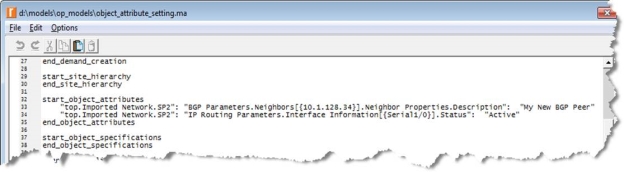
If you are specifying a value in a compound attribute, use curly braces in attribute names to specify which row in a compound attribute table to use. The text inside of the curly braces will be matched against the primary key of each row in the table. The primary key is almost always the first column in the table. This is easier than identifying the index of the row.
Figure 52: Specifying a Compound Attribute Value
To load a particular model assistant file within the editor, click on Load... and choose the .ma file you wish to edit from the Select a Model Assistant File to Load dialog box.
Figure 53: Load Model Assistant File
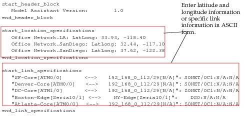
After selecting and loading a model assistant file, click on Edit in Text Editor to view an ASCII version of the file, as shown below. In this example, you can see the anatomy of site location specifications and site link specifications.
Figure 54: Model Assistant File in ASCII Format
To insert an entry into the ASCII version of a model assistant file, simply add a line to the file, using the syntax required for each data type. For example, if you want to add an attribute in the Object Attributes block, use the following syntax:
start_object_attributes
	“top.node_0”:	“IP Routing Parameters[0].Default Gateway”:	“1.1.1.1”
end_object_attributes
Note that the syntax is the exact hierarchical object name (top.node_0), the exact attribute name (IP Routing Parameters[0].Default Gateway), and the exact attribute value (1.1.1.1). Each entry is enclosed in quotation marks and is separated by colons. The sub zero [0] shown after “IP Routing Parameters” in the example shown above indicates the row number of the attribute. For example, if you have twelve rows in the compound attribute “IP Routing Parameters[0].Interface Information”, you need to be sure to place the sub(n) row number after the attribute (i.e., “IP Routing Parameters[0].Interface Information[11]” indicates the twelfth row in the node attribute).
You can edit the text version of the model assistant file or you can edit the file from the UI, as described in Procedure 48.
Note: When entering attribute names and values through the UI, do not use quotation marks.
After creating a model assistant file, you can apply it to a scenario by selecting the file during Device Configuration Import (DCI) or by following Procedure 50.
Note: DCI requires that you have eXpress Data Import functionality.
Applying a Model Assistant File to a Scenario
The following procedures describes how to apply a Model Assistant file to a scenario.
Procedure 50: Applying Model Assistant Data to a Scenario
-
Open the project and scenario you want to update.
-
Apply the model assistant data using one of the following methods:
- If you want to apply a model assistant file without editing it, choose Topology > Model Assistant > Apply File…
- If you want to create a new file or edit an existing file, see Editing a Model Assistant File.