Preparing for the Import
This section introduces the pre-import workflow, including preferences, caveats, and troubleshooting tips that are helpful for preparation before you import your device files. Paying careful attention when planning for an import can help reduce post-import issues.
Creating the Configuration Files
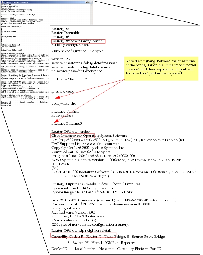
Before importing configuration files into NetPlanner, you must first generate the files from the configuration information on each device. The configuration files are created by running a few commands, which are listed in Table 2, on the router or switch and copying the output to a text file, as shown in Figure 1.
You can abbreviate certain show commands on the device. The show version, show interfaces, and show standby commands can be abbreviated to
sh[o][w] ver[s][i][o][n]sh[o][w] in[t][e][r][f][a][c][e][s]sh[o][w] st[a][n][d][b][y]
For example, show version could be input as:
LAB-Voice6500-B#sh ver
Note: If there is no space between the device prompt and the show command, DCI only recognizes > or # prompts, that is, if the prompt is anything else, the command will not be read properly by DCI during import. However, if there are one or more spaces prior to the show command, DCI ignores the prompt and reads the output as expected.
To see the procedures for collecting the device configuration files, refer to the procedures in “Additional DCI Procedures“ on page 1.
Table 2: Show Commands Used by DCI
| Order | Command | Importance | Usefulness |
|---|---|---|---|
| 1 | show running-config | Required for Cisco routers and PIX devices | The output from this command carries the basic information about the Cisco router, PIX firewall, or IOS device, interfaces, and configuration. |
| show configuration | Required for Juniper routers | The output from this command carries the basic information about the Juniper device, interfaces, and configuration. | |
| show config all | Required for Cisco Catalyst Switches | The output from this command carries the basic information about the Cisco Catalyst switch configuration. | |
| 2 | show version¹ | Recommended² | DCI uses the output from this command to determine the type of device from which it was collected and configuration for the System Information compound attribute. |
| 3 | show cdp neighbors detail | Required for Cisco switches; Optional for Cisco routers | DCI uses the output from this command to determine connectivity between neighboring devices. |
| 4 | show interfaces | Optional but recommended for Juniper routers, Cisco routers; PIX firewalls; switches running Native IOS, RSM, or MSFC | Recommended to set interface MTU and metric information (bandwidth and delay) on interfaces. These values are used in OSPF and EIGRP for routing calculation. |
| 5 (in any order) | show vlan | Required for Cisco switches running IOS and CatOS | DCI uses the output from this command to determine the supported VLANs on the device. |
| show vtp status | Required for Cisco switches running IOS and CatOS | DCI uses the output from this command to map VTP parameters on the switch. | |
| show frame-relay map | Required to replicate static Frame Relay PVCs in model | DCI uses the output from this command to create Frame Relay PVCs in the network model. | |
| show atm map | Required to replicate static ATM PVCs in model | DCI uses the output from this command to create ATM pvcs in the network model. | |
| show standby | Optional for Cisco routers and Cisco switches running Native IOS, RSM, or MSFC | Used to determine the operational status of HSRP groups on this device. | |
| 6 (optional) | show ip route | Required to create routing tables for devices in model | DCI uses the output from this command to create routing tables that can be used during simulations. Note: Must be placed at end of configuration file. |
| show ip route protocol | Required to create protocol-specific routing tables for devices in model | ||
| show ip mroute | Used by Cisco routers to create multicast routing tables for devices in model. | ||
| show multicast route extensive | Used by Juniper routers to create multicast routing tables for devices in model. | ||
| show ip route vrf vrf | Required to create VRF forwarding tables for devices in model | ||
| show ip route vrf vrf protocol | Required to create protocol-specific forwarding tables for devices in model | ||
| 7 | show ip igmp group detail | Optional | DCI uses the output of this command to determine the operational status of multicast groups on this device. |
| 8 | show mpls traffic-eng tunnels | Optional but recommended for Cisco routers and multilayer switches, if using the auto-bandwidth option | DCI uses the output of this command to populate the auto-bandwidth command on MPLS tunnels. |
| show mpls lsp extensive | Optional but recommended for Juniper routers, if using the auto-bandwidth option | ||
| Multi-Layer Switches with Dual MSFC | |||
| 1 | show version | Required on supervisor engine and MSFC(s) for switches with Hybrid OS | DCI uses the serial number from the output of this command to correlate the MSFCs to the switch and to populate the System Information compound attribute. |
| 2 | show module | Required on switches with Native IOS and on supervisor engine for switches with Hybrid OS | DCI uses the output from this command to determine the presence and serial numbers of MSFCs. |
| 3 | show redundancy | Required on MSFC(s) for switches with Hybrid OS | DCI uses the output from this command to determine which of two MSFCs is designated. |
Note 1: Show version is now supported for PIX firewall.
Note 2: Memory information is imported for Cisco devices only.
Figure 1: Creating Device Configuration Files
Creating Device Models (Optional)
During the import, DCI searches the model directories for the device model that best matches each configuration file. Typically, this model has more interfaces or ports than the actual device. You can create a set of device models with the same number and type of interfaces as the devices you are importing. Doing this ensures that the models chosen during import match the actual routers or switches exactly.
You can use the Device Creator to create these models, as described in “Create Custom Device Model” on page 204. This step is optional, but it gives you the greatest control over the devices chosen by DCI to represent the imported devices.
Importing Multi-Layer Switch Configurations
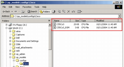
In preparation for any device configuration import, you must be sure to gather all the device configuration files necessary to build an accurate topology. It is default DCI behavior to skip a device for which a partial configuration is found. For import of a Layer-3 switch, two device configuration files are required.
Figure 2: Configuration Files Required for Multi-Layer Switch
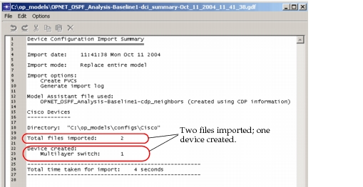
After import, the files create one device in the network model, as shown in the following figure.
Figure 3: Import Summary - Multi-Layer Switch
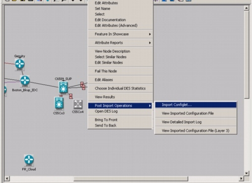
When you want to view the source files for the device, the menu choices include both files. You can view source files for both the Layer-2 portion of the device and the Layer-3 portion. Similarly, you can view the import log generated by the import of each configuration file, as shown in the following figure, yet the two files make one node in the model:
Figure 4: Source Files and Import Log - Multi-Layer Switch
If a multi-layer switch configuration file is examined during import and found to have an active (not shutdown) VLAN interface for which no corresponding switch configuration file is located, however, DCI will skip the import of the entire device with an error message: “File name: my-file-name.txt File skipped because Layer-2 configuration file is not available for the multi-layer switch ‘my-host-name’.”
If you want to change the default behavior, so that no devices will be skipped during import, you need to change the Skip Router Switch Devices with Partial Configs preference, as described in Setting Device Import Preferences.
Importing Cisco 6500 Multi-Layer Switches with Dual MSFCs
NetPlanner supports Cisco 6500 series multi-layer switches with dual Multilayer Switch Feature Cards (MSFC). These switch types are imported into the network model as multi-module switches, as shown in the following figure.
Figure 5: Multi-Module Switch in Network Model
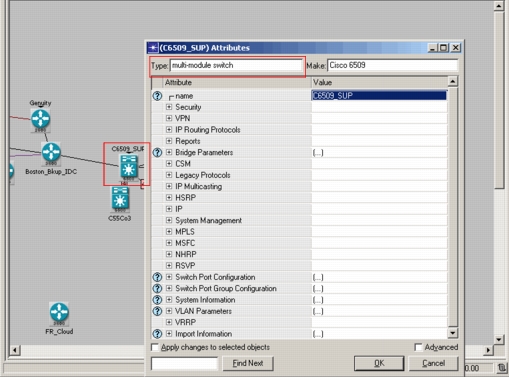
The MSFC adds routing functionality to the switch. With dual MSFCs, the multi-layer switch has redundancy capabilities that can be configured in different ways, depending upon the OS type: Native IOS or Hybrid OS. The following table lists the various configurations and the files required during import:
Table 3: Required Files per Configuration Type in Cisco Catalyst 6000 Switches
| OS Type | Router Mode | Redundancy Mode | # of Active Routing MSFCs | Config Files Required |
|---|---|---|---|---|
| Hybrid OS | Dual | Config Sync Enabled | 2 | - One IOS Config File - One CatOS Config File |
| Config Sync Disabled | 2 | - Two IOS Config Files - One CatOS Config File |
||
| Single | Not Configured | 1 | - One IOS Config File - One CatOS Config File |
|
| Native IOS | Single | SSO—Stateful Switchover | 1 | - One IOS Config File |
| RPR—Route Processor Redundancy | 1 | - One IOS Config File | ||
| RPR+—Route Processor Redundancy Plus | 1 | - One IOS Config File |
Note: Cisco Catalyst 5500 multi-layer switches with dual route switch modules (RSM) are imported as multi-module switches with only one RSM configuration file.
Once the dual-MSFC devices are imported, the network model reflects the configurations in the following way.
Table 4: Model Attributes for Device Configurations
| OS Type | MSFC Parameters.MSFC Mode | Non-Designated Router Compound Attribute |
|---|---|---|
| Native IOS (Single Router) | - Native-SSO - Native-RPR - Native-RPR+ |
Not applicable. |
| Hybrid OS, Single Router Mode | Hybrid-SRM | Not applicable. |
| Hybrid OS, Dual Router Mode (Config Sync Enabled) | Hybrid-DRM Configuration Synchronization: Enabled |
Contains the configuration for the non-designated MSFC. |
| Hybrid OS, Dual Router Mode (Config Sync Disabled) | Hybrid-DRM Configuration Synchronization: Disabled |
Not configured. |
| Hybrid OS, Independent MSFC Devices (No redundancy) | Hybrid-Independent | Not configured. |
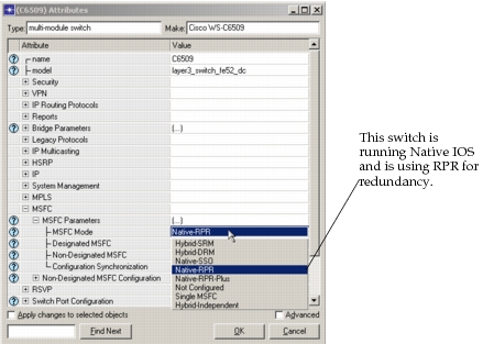
After import, you can see the type of redundancy that is configured by examining the MSFC Mode attribute, shown in the following figure.
Figure 6: MSFC Mode Attribute
Hybrid OS
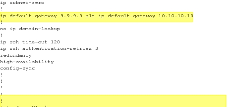
As you can see from Table 3, in a multi-layer switch using Hybrid OS, you can configure redundancy on a switch that is in dual router mode (DRM) by enabling or disabling config sync. When config sync is enabled, one configuration file serves both MSFCs, with the “alt” keyword separating one MSFC configuration from the other. A sample configuration is shown in the following figure. In this case, both the designated and non-designated router configurations are imported and available.
Figure 7: Sample Configuration—Dual MSFC/Config Sync Enabled
When config sync is disabled, each MSFC has its own configuration file, although both files must share some attributes in common, per Cisco requirements.
Import considers dual MSFCs in terms of designated and non-designated status. The designated MSFC is the one that came up first or has been up the longest. The non-designated MSFC is actively building routing tables but does not control the forwarding table.
When a switch is in single router mode, only one MSFC is active and visible to the network. The other MSFC provides hardware redundancy only.
Native IOS
A multi-layer switch using Native IOS is always in SRM and has redundancy configured in one of three ways:
- Stateful switchover (SSO)
- Route processor redundancy (RPR)
- Route processor redundancy plus (RPR+)
Note: Figure 6 shows the supported redundancy modes.
The following figure shows that a multi-layer switch with dual MSFCs contains two compound attributes: MSFC Parameters and Non-Designated MSFC Configuration.
Figure 8: MSFC Configuration
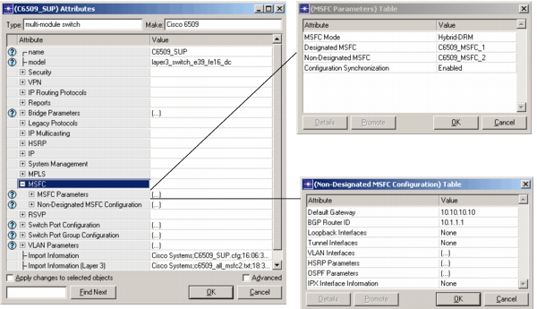
The exact attribute mapping and supported commands are described on the OPNET Support website. Go to the Product Resources page for NetPlanner, then go to the section on Supported Vendor Protocols and Commands.
For information on the “show” commands required to properly import devices with dual MSFCs, see Table 2.
Restricting Import to Layer-3 Devices
You can set a preference to import Layer-3 devices only. When this preference is enabled, DCI will include these devices types in the imported topology:
- Routers/Layer-3 modules (IOS/JUNOS)
- Router-Switches (Hybrid OS/Native IOS)
- PIX Firewalls
It will not include
- Catalyst Switches (CatOS)
- IOS Switches
To enable this preference, set the Import Layer-3 preference to TRUE, as described in Setting Device Import Preferences.
Note: Router-Switches will only have the Layer-3 components imported when this preference is enabled.
Inferring Layer-3 IP Clouds
Tunnel interfaces in your network can have physical connectivity through Layer-2 devices where you do not have network access. During a DCI import, Layer-3 IP clouds are inferred for these tunnel interfaces when there is sufficient IP tunnel information in your available configuration files. This is often true when Frame Relay or ATM is configured in a network and the physical path of the link goes through a leased ISP network. By default, DCI will include these inferred Layer-3 IP clouds in the imported topology.
Note: During import, if you choose “Reimport configuration for selected devices” or “Reimport configuration for modified devices” in the Import Device Configuration dialog box, the Layer-3 IP clouds will not be inferred.
To change this preference, set the Create Tunnel Clouds preference as described in Setting Device Import Preferences.
Importing VoIP Devices
If you are importing VoIP devices into your network, set the preference Import VoIP Configurations as described in Setting Device Import Preferences.
Setting Device Import Preferences
Several device import preferences influence the way files are imported and parsed during DCI. The preferences are detailed below:
Note: Device import preferences are not visible until you have performed at least one device configuration import. If you have not done an import, you can begin an import and cancel out. The preferences then become available.
-
Save Configs with Project—Specifies whether to backup the device configuration files during import. In previous versions, all files imported during device configuration import were automatically backed up into a new folder called
<project-scenario>.cfd.dir. In the case of large numbers of nodes, making this backup could take a long time. You can control whether to backup the files. The choices are as follows:- TRUE—This is the default value. If the preference is set to TRUE, configuration files are backed up.
- FALSE—If the preference is set to FALSE, the configuration files are not backed up during import.
-
Import Layer-3 Only—Specifies whether to import all device types or Layer-3 device types only. The choices are as follows:
- FALSE—This is the default value. If the preference is set to FALSE, all device types are imported (Layer-2 and Layer-3).
- TRUE—If the preference is set to TRUE, only Layer-3 devices are imported.
-
Skip Router Switch Devices with Partial Configs—Specifies whether to import devices for which a partial configuration is available. The choices are as follows:
- FALSE—This is the default value. If the preference is set to FALSE, devices with partial configurations are imported.
- TRUE—If the preference is set to TRUE, devices for which only a partial configuration exists are skipped during import.
-
Use Configured Bandwidth for Datarate—Specifies whether import should use the bandwidth statement to set the datarate on a link.
- TRUE—If the preference is set to TRUE, the bandwidth statement is used.
- FALSE—This is the default value. If the preference is FALSE, then any explicit commands used in the device configuration to set the link speed are used to infer the datarate.
-
Display Complete Path for Configlet Files—Specifies whether the full path or only the configlet file name is displayed in the Apply Configlets dialog box.
- TRUE—If the preference is set to TRUE, the entire path is shown.
- FALSE—This is the default value. If this preference is set to FALSE, only the configlet file name is shown.
-
Create Copy of Configlet File Applied to a Device—Specifies whether to save a copy of newly assigned configlet as part of the project-scenario. The default value is FALSE.
- TRUE—If the preference is set to TRUE, the configlet files are copied to the project-scenario directory.
- FALSE—The default value is FALSE. If the preference is set to FALSE, the configlet files are not copied to the project-scenario directory.
-
device_import.collapse_clouds—Specifies whether imported clouds are viewed as a single cloud by collapsing all subnets or as subnet clouds collapsed by protocol. The choices are as follows:
- Don’t Collapse—Default behavior that imports clouds with different IP subnets as separate clouds.
- Collapse All—Imports all clouds into a single subnet called “Network Cloud”.
- Collapse per Protocol—Creates cloud nodes in subnets by protocol. ATM clouds are collapsed into a subnet called “ATM Cloud”. Frame Relay and serial clouds are collapsed into a subnet called “Serial Cloud”.
Note: You must add this preference to your preference file before you can set it. See Procedure 5 for more information.
-
Create Serial Clouds—Specifies whether to convert a cloud that is a mixture of Frame Relay, ATM, and serial into a serial cloud. Possible selections are as follows:
- TRUE: The following mix of interfaces is converted to a serial cloud—ATM + Frame Relay, ATM + Frame Relay + Serial, ATM + Serial, or Frame Relay + Serial. A model assistant file with the information necessary to link the interfaces is created during the initial import of the model. You must do a second import of the network model using the model assistant file that is created during the first import to complete your model.
- FALSE: ATM + Frame Relay is imported as a combined FR/ATM switch. Other connectivity is not inferred. If Ethernet interfaces are present, no cloud is inferred.
-
Create Tunnel Clouds—Specifies whether to infer Layer-3 IP clouds. Possible selections are as follows:
- TRUE—This is the default value, which will infer Layer-3 IP clouds based on the tunnel interface information in the import file.
- FALSE—This option will not infer Layer-3 IP Clouds. Tunnel interfaces will not be connected in the network model when there is no information about Layer-2 connectivity between the interfaces.
-
Import VOIP Configurations—Specifies whether a VoIP device is imported as a multi-service switch or as a router. Possible selections are as follows:
- ENABLED: (default) If the preference is set to ENABLED, the VoIP device is imported as a multi-services switch. All VoIP configurations are imported, and attributes are set as expected.
- DISABLED: If the preference is set to DISABLED, the VoIP device is imported as a router. All VoIP configurations are ignored, and a message is created in the import log.
-
Create Logical Subnets—Specifies whether to create logical subnets during import. Logical subnets differ from typical subnets with respect to the concept of span. Logical subnets have infinite spans starting from (0,0). The position of any node or subnet within a logical subnet is based on the pixel location within that subnet. Therefore a node or subnet cannot reside in the negative x or y location. With logical subnets, no bounding box is created, which normally results in lines in the project editor delineating the span.
- TRUE—(default) If the preference is set to TRUE, logical subnets are created during import.
- FALSE—If the preference is set to FALSE, no logical subnets are created, and the project editor has a normal span with a bounding box.
Note: If a background map or location information is included in the VNE Server data, the value of this preference is ignored during import.
-
DCI Parser Status Timeout—Specifies the interval in seconds at which the status of the import is checked. If the Java process does not respond for 3 consecutive status checks, the import is cancelled.
- Default: 10
- Tag: device_import.parser_status_timeout
-
DCI Parser Init Timeout—Specifies the time in seconds allowed for the Java process to start up
- Default: 60
- Tag: device_import.parser_init_timeout
-
DCI Parser Port—Specifies the port used by XDI to connect with the Java parser process on the local machine
- Default: 3101
- Tag: device_import.parser_port
Note: If the NetPlanner installation is on Linux, and you have any other process using port 3101, you must change the preference DCI Parser Port preference and the NDMS.XMLCOM.HTTP_PORT in $sys/utilities/dci_parser/lib/xml/dtd/props_platform_based.dtd to a port that is not in use.
-
DCI Parser Memory Size—Specifies the maximum amount of memory in MB that the Java parser process can use
- Default: 1116 (1GB)
- Tag: device_import.parser_max_memory