Path Editor Dialog Box
The Path Editor lets you define path models; each path object’s underlying model determines its attribute interfaces, presentation, and behavior.
The following figure shows the Path Editor dialog box, in which you create or modify the path model specifications described in this section.
Figure 213: Path Model Editor
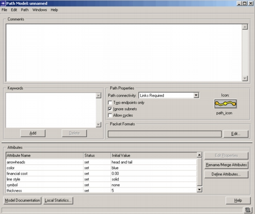
A path model specifies the following information:
-
Path Connectivity – At the very minimum, a path object defines the two sites where the path begins and ends; it may also define a specific route between these two nodes. The Path Connectivity pull-down menu includes three options that define whether you can (or must) include link objects when defining a path based on that model.
The Links Required option specifies a complete route definition. When defining a path with this setting, you must specify connecting links between all sites in the path.
The Links Ignored option means that you cannot specify any links connecting sites in the path. The underlying protocol models determine the specific paths taken by packets from one site to the next.
The Links Optional option specifies that specifying links between any sites is optional. Protocol models route traffic through any undefined parts of the path.
-
Number of segments – With the Two Endpoints Only option set, you can only define single-segment path objects. If you want to create a path with more than two sites and a connecting link, this box should be unselected.
-
Subnets Ignored – With this option set, the path object cannot include subnetwork objects. (However, you can still include nodes from different subnets in the same path.)
-
Allow Cycles – With this option set, the path object can include the same link or node multiple times.
-
Packet Formats – Each path has a defined set of supported packet formats. You cannot define a link as part of a path unless that link supports all formats included in that path model’s Packet Formats field. (Note that if a path supports no packet formats, you can include any link in the path definition.)
-
Keywords – Model keywords allow you to selectively display models that meet certain characteristics in the Project Editor object palette. You can define any number of keywords to define a path’s characteristics.
-
Model Comments – Each path model contains a set of comments that describe its characteristics, potential applications, and any information that may be of interest to a user of the model. Because users of other OPNET solutions do not have access to path model internals, the comments may provide the primary information about the model’s capabilities and interfaces. Embedding documentation on the model’s interfaces as an intrinsic part of the model itself provides convenient access to information for model users and helps to ensure that model documentation remains consistent with a model as it evolves through different phases of development.
-
Attribute Interfaces – Path models can provide specifications for the attributes of path objects in the Project Editor. Like link models, path models contain no objects that can promote attributes; therefore the only attributes that a path can promote are the “path model attributes” described later. Like a link model, a path model can specify configuration information for built-in attributes of the path object. Specifically, operations that are possible are attribute pre-assignment, attribute hiding, attribute renaming, and changing of attribute properties.
For more information about these mechanisms, see Chapter 4 “Modeling Framework” on page 80.
-
Model-specific handlers – Allows you to change the default behavior when a user changes or otherwise accesses (clicks, right-clicks, etc.) a path. You can specify a custom ETS library and event handlers by clicking the ETS Handlers button.
-
Local Statistics – The Local Statistics button is functionally equivalent to choosing Local Statistics from the Path menu.
For more information, see Local Statistics.