Process Model Development Methodology
Other parts of this section provide information about the capabilities of the Proto-C language and the specification features of the Process Editor. It should be clear from these that Proto-C provides a flexible platform that has the ability to model a wide range of systems. The language provides specific support by adopting a state-transition approach which is well-suited to discrete event systems, and by supplying a number of Kernel Procedures (KPs) that are oriented toward network and distributed systems modeling. At the same time however, Proto-C preserves generality by incorporating all the capabilities of the C/C++ programming language.
Due to the generality of Proto-C and the flexibility of the state-transition paradigm, most systems can be accurately represented by many different Proto-C models. The diversity of possible implementations results from the power of the tool but can also present some disadvantages; namely, the model designer may experience hesitation at the start of a model’s development effort, as the merits of each approach are considered. This is particularly true in the case of a beginning Modeler user. In addition, the models that one developer creates over time may vary in approach rather than converge on one consistent style; this adds difficulty to the future task of maintaining the models, particularly if different developers are involved.
To reduce problems related to the variability of potential approaches, this section provides one development methodology that is applicable to process models of all types. The goal of the methodology is not to limit the extent to which Proto-C’s capabilities are used, but rather to lend structure to the development process so that the full set of capabilities are used consistently and correctly. It is particularly recommended that beginning users follow this methodology to quickly advance to the point of developing complex models. Advanced users may want to continue practicing this methodology so that development becomes a consistent and therefore routine process.
Note that use of the methodology presented here is not mandatory; the information in the first part of this section is sufficient to serve as the basis for development of process models in Proto-C. This methodology presented here is merely a suggested approach that developers may want to consider.
Description of Example Systems
Because section describes a methodology that applies to process model design in general, many of the procedures that are prescribed are stated in terms that might at times seem abstract. To give these procedures a more concrete form, several simple examples of processes are used throughout the section.
Pay Telephone System
This example process is responsible for managing the usage of a simple coin-operated telephone. The process must respond to the actions of both the telephone user and the network to which it is connected. In particular, it is responsible for the following:
- Providing a dial tone to the user after a minimum amount of money has been deposited and the network has acknowledged the request for use of the line.
- Informing the network of the amount of money that has been deposited.
- Relaying a dial tone signal from the network to the user.
- Relaying the user’s phone numbers into the network if a dial tone has been established (otherwise keystrokes are ignored).
- Warning the user when money runs out and informing the user when they are finally disconnected (the network provides the process with a notification Warning_Time seconds before the user’s time has run out).
- Returning money to the user if the network indicates the call is toll-free or the user hangs up before the destination party answers.
The process resides in the telephone unit itself and therefore manages at most one phone call at a time.
Automatic Bank Teller System
The process of interest manages the transactions requested by one user via a keypad. The supported transactions are deposits, withdrawals, and balance verification. In all three cases, the user must insert a magnetic card and authenticate the card’s usage by entering an identification number on the keypad.
The bank teller process controls five physical devices: (1) the card reader; (2) the deposit door; (3) a text-oriented display to convey information to the user; (4) the cash dispenser; (5) the report printer.
In addition, the process has the ability to communicate with another process representing the bank. This remote process supports the following set of transactions:
- authenticate_request – expects the card’s serial number and the user’s personal ID number to be passed and either sends back a rejection indication, or an account handle that can be used for transactions.
- withdrawal_request – the bank returns an authorization code if the withdrawal is allowed.
- deposit_indicate – informs the bank that a deposit has taken place.
- balance_request – the bank returns the user’s current balance.
Medium Access System
A simple medium access method is used by the multiple transmitters that share a channel. Each transmitter must abide by the following rules when trying to transmit a message over the medium:
- A transmission may not begin until the medium has been idle for Gap_Time seconds, where Gap_Time is a parameter whose value is to be defined.
- If during a transmission, the transmitter unit detects that another message is present on the medium, then the transmission is immediately aborted and attempted again not before R seconds, where R is a uniformly distributed random number between zero and Backoff_Time. The same rules of transmission (e.g., idle-time restrictions) apply to repeat attempts as to initial transmissions.
- If otherwise unrestricted, a transmission necessarily begins after the medium has been idle for Gap_Time seconds.
- There is no limit on the number of times a message may be retransmitted.
- Transmission requests that are submitted to the process are transmitted in a first-in-first-out order. The process’ queue of messages that await service is considered infinite.
Data Link Control System
One outgoing transmission line contains N logical channels, where N is a number that may change dynamically. Each logical channel is equipped with a data-link layer protocol that ensures the correct reception of transmitted messages. Reception is guaranteed by using an acknowledgment-based scheme which operates according to the following:
- Each message is transmitted repeatedly every Timeout seconds until an acknowledgment message that specifically identifies it is received from the destination.
- If Max_Attempts transmissions have failed, the message is discarded.
- Messages are processed in a first-in-first-out order and the message queue is considered to have infinite capacity.
This data-link protocol operates independently for each logical channel.
Stage 1: Defining the System's Context
In almost all cases, process models describe the behavior of one component within a larger system model, consisting of many components. The role of the process model can then generally be described by the interactions that it has with the other components in the system. From the point of view of the remainder of the system, only the external “black-box” behavior of the process is of concern, not its internal implementation. It is therefore an important first step in the development of a process model to identify the other system components that it will interact with.
Identifying Interdependent Modules
Because processes operate within modules in the node domain, the term components refers to other modules. To refer to these components in general, the term interdependent modules is used. If the interdependent modules are processors or queues, then their behavior is also determined by a process model.
Because processes are event-driven, all modules that generate events for the process of interest should be considered interdependent; in addition, all modules that receive information from or store information for the process of interest should also count as interdependent, because they play a role in the evolution of the process over time. Note that interdependent modules are not limited to physical neighbors of the process’ module. For example, modules that are not connected, or even those that are in different nodes, may communicate by delivering packets or sending remote interrupts to each other. See “Communication Mechanisms” for more information about these types of interaction.
In some cases, interdependent modules are not all known in advance at the time that a process is designed. In fact, some processes may be designed to handle interactions with an unlimited number of other modules. In such cases one or more representative modules should be included in the design.
Before beginning the actual design of the process of interest, all of the interdependent modules, including the module whose process is under design, should be placed together in a diagram. Modules need not be identified by their name, but rather by their function relative to the process of interest. For modules that may appear in variable numbers, ellipses can be used to represent a group.
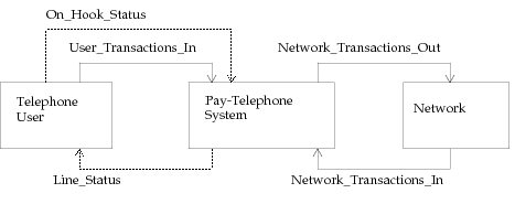
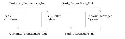
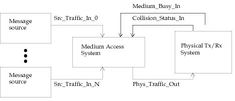
The following sketches depict the physical contexts of the four example systems. Note that at this stage of the design, such diagrams may be developed manually, or within the Node Editor. Ultimately, however, the physical context of the process is always defined by a node model diagram created with the Node Editor.
Figure 120: Interdependent Modules of Pay-Telephone System

Figure 121: Interdependent Modules of Bank Teller System

Figure 122: Interdependent Modules of Medium Access System
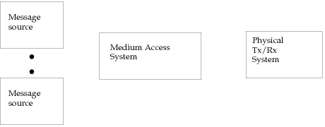
Figure 123: Interdependent Modules of Data Link Control System

Selecting Communication Mechanisms
Having established which other modules a process would interact with, the developer may proceed to decide the communication mechanism that will be used on each interface. A number of communication methods are available; the most commonly used ones are briefly reviewed here. See “Communication Mechanisms” for more complete information about these options.
-
Packet communication – Packets are messages whose contents are formatted into individual fields that carry information. This is the most common form of interface between modules because it naturally corresponds to the message-based communications that occurs in many networks and distributed systems.
Packet communication is a sensible choice for any interfaces that transfer messages in the actual system being modeled. In addition, because packets can store arbitrary user-specified information, they can be used to represent general transactions such as commands between processors, requests for resources, tasks with associated parameters, etc. Note however, that other supported forms of communication may be more appropriate than packets, depending on the application.
Packets may be sent to other modules in the same node via connecting packet stream objects, or they may be sent to modules anywhere in a model with packet delivery (see the documentation on op_pk_deliver() and related KPs in “Discrete Event Simulation API”.
-
Remote interrupt – This is a lightweight form of communications because it does not necessarily transfer a data structure with it, as packet communication does. Remote interrupts may be sent to modules within the same node or in others to indicate simple information such as the status of a semaphore, or value of a variable. In addition, ICIs, which are formatted groups of values, can be associated with remote interrupts to allow them to convey general information to a destination process. This makes remote interrupts suitable for modeling transactions such as requests and indications, parameterized commands, etc.
Packets can also be used for many of the same types of tasks as the remote interrupts / ICI combination because they can contain general data. However, ICIs incur less overhead and are generally more appropriate if the data that traverses the interface is confined to the two modules of interest (i.e., does not later progress to other destinations). Note, however, that packets have the additional flexibility of supporting transfer over physical packet streams which implicitly guide the data to a destination that is determined by the configuration of the surrounding node model; this allows the process model to be developed in a more abstract fashion where data is sent out via ports without specific knowledge of which modules will be the destination.
-
Access interrupt: This communication mechanism is used in conjunction with packet communication because it requires the presence of a packet stream object. Like a packet being sent, an access interrupt is issued by specifying the index of a packet stream, without necessarily having specific knowledge about the object that is connected. However, access interrupts travel backwards on streams, generally to request that a stream’s source request a packet. The interrupt is commonly used in configurations where a queue module is a stream source, and the stream’s destination module requests packets from the queue; this is referred to as a passive queue configuration and should be used when a process is not able to asynchronously accept packets.
-
Statistic communication: Statistic wires can be placed between module output statistic ports and the input statistic ports of processors and queues. They provide processes in the destination module with a capability to do “live” monitoring of the output statistic value. In addition, statistic wires provide triggers which allow asynchronous interrupts to be generated for the destination module when certain patterns of change occur in the monitored statistic. Statistic wires are generally used to alert processes of situations that need attention (such as a queue approaching overflow), or to allow processes to make use of up-to-date performance and behavioral information in adaptive algorithms.
When designing a module’s process models, any combination of the above communication mechanisms may be used with one or more other modules. Three of the four described interface types above make use of physical ports belonging to the module whose processes are under design. If any of these physical interfaces are employed, each port should be assigned a name for reference in later stages of the design. It is generally helpful to depict all interfaces to and from the module of interest, whether physical or abstract, in the node-level diagram that contains the interdependent modules. The names of the physical interfaces should be placed near the associated input and output ports.
Application to Examples
This section uses each of the four example systems defined elsewhere to illustrate the definition of the physical contexts of processes.
Pay Telephone System
In the case of the pay-telephone system, packets are the only necessary form of communicated data. ICIs with remote interrupts could be used, but this would require assumptions concerning the outgoing interface to the network, because the pay-telephone process would have to know where the network process is located to schedule interrupts for it. By using packets, the pay-telephone process may rely on the outgoing packet stream labeled Network_Transactions_Out to somehow guide the packet to the network process. This packet stream may lead to a process in the same node or to a transmitter that uses a link to reach the network process in another node; the details of this are not of concern to the pay-telephone process. In addition, the process can receive packets representing actions taken by the user (e.g., coin-deposit, phone number entry) over the packet stream labeled User_Transactions_In. The on-hook or off-hook status of the phone is represented instead by a statistic wire because it is a simple boolean variable; note however, that use of the statistic wire relies on the assumption that the user process is in the same node as the pay-telephone process and that this assumption could be avoided if the on-hook status information were simply incorporated into the packets arriving via User_transactions_In. Responses and status information from the network arrive over the packet stream Network_Transactions_In. The use of a stream here is symmetric with the outgoing interface to the network and preserves the flexibility of placing the network process anywhere. Finally, Line_Status is an outgoing statistic wire that indicates information to the user process such as whether the line is available, and the call-nearly-over warning.
Figure 124: Physical Context of Pay Telephone System
Bank Teller System
For the bank teller process, it is assumed that the actions having to do with operation of the various physical devices can be communicated to the customer process via one packet stream interface called Customer_Transactions_Out. Packets would contain information identifying the affected device and any associated parameters (e.g., device = DISPLAY, text = “please enter transaction type”). All other incoming and outgoing interfaces are also based on packet communication to allow placing the processes in arbitrary locations that are selected when the modules are deployed (e.g., the processes could be in different nodes).
Figure 125: Physical Context of Bank Teller System
Medium Access System
The medium access system can receive packets submitted for transmission over any number of stream interfaces labeled Src_Traffic_In_0 through Src_Traffic_In_N. When the process decides to send a packet onto the medium it can do so via the outgoing packet stream interface labeled Phys_Traffic_Out. The process also needs to be apprised of two types of status information for the medium. The Medium_Busy_In statistic wire allows the process to determine if the medium is currently carrying any transmissions; the Collision_Status_In statistic wire informs the process if two or more transmissions are simultaneously occurring on the medium.
Figure 126: Physical Context of Medium Access System
Data Link Control System
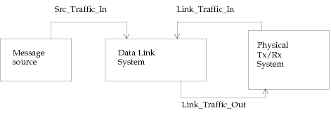
The multiple channels of the data-link control system are logical channels so the assumption is made that the messages arrive over one physical interface labeled Src_Traffic_In in the form of packets. The packets must therefore carry some information allowing the process to determine which logical channel they belong to. The mechanism by which packets are actually placed on a particular logical channel is left to the transmission subsystem to which packets are sent by using the output stream labeled Link_Traffic_Out. Packets arriving from the link are expected on an incoming packet stream labeled Link_Traffic_In.
Figure 127: Physical Context of Multi-Channel Data Link Control System
Stage 2: Process Level Decomposition
Each queue or processor module can contain multiple processes and the number of processes can vary as a simulation progresses. The purpose of this stage of the design procedure is to determine if the behavior of the module of interest should be implemented by one process model or by multiple process models, and in the latter case, what the function of and relationship between the process models would be.
Decomposition Techniques
It is always possible to implement the desired behavior of a module by means of one process. However, there are many modeling situations that are greatly simplified and more intuitively approached by applying Proto-C’s dynamic process paradigm. In general, multiple processes should be used when:
- The number of processes in the module must scale in response to dynamic requirements.
- The module must manage multiple tasks that operate asynchronously.
- A top-down approach is required to reduce complexity or to defer detailed implementation.
Replication of Identical Processes
This is a common situation in communications systems where one physical device may be involved in processing a large number of identical ongoing threads. A thread is an ongoing activity that maintains state. Common examples are a telephone call, a virtual circuit in a packet-switched network, or a session of a transport layer protocol. In modeling computing systems, threads may appear as programs that are run under a multitasking operating system, or as sub-tasks of those programs.
The requirement that a module should execute a dynamic number of processes of the same type is generally quite clear from the specification of a modeling problem. The key system feature associated with this type of scenario is the fact that a variable number of users of the module receive service on an essentially independent basis. A user is not necessarily another module, but should be a source of activities for the module. For example, one traffic source could generate multiple packets representing initiated telephone calls and attribute them to different users by placing a user identification in a field of the packet. Each call would then be processed independently when it is received by the module of interest. Therefore, even though there is only one source module, it acts as a model of multiple users that generate activity for the module being designed.
The approach for this type of module is to create a process model that implements one thread. A higher level process, usually the root, detects conditions that require the initiation of new threads (e.g., a new telephone call request is received) and uses the KP op_pro_create() to create processes to represent them. If a thread evolves to a point where it is no longer needed (e.g. the telephone call parties hang up), it can be terminated with the KP op_pro_destroy(), either by itself or by a master process.
Asynchronous Cooperating Tasks
Certain processes can be divided into several smaller processes that operate asynchronously but cooperate to accomplish a common goal. Asynchronous operation refers to the fact that the processes have separate event-processing threads that are driven by differing sequences of events. The processes may depend on one another for information and may even generate events for each other; however to be considered asynchronous, at least part of the processes’ timing should be independent. If instead, all processes are executed in lock-step (i.e., at the exact same times), then they can easily be subsumed into one process that manages all of their activities.
Using dynamic processes, Proto-C provides a very natural way to address the modeling of this type of system. The developer must divide the activities of the module of interest into separate functional areas, keeping in mind the guideline that each functional area should have not only different responsibilities, but distinct timing as well. Each functional area can then be implemented by a distinct dynamic process with its own state. The processes can also share information, using the various process hierarchy memory mechanisms described earlier in this section.
This approach requires delimiting the functional areas by assigning names to them and listing the activities for which each one is responsible. In addition, the relationships between the processes should also be defined in a general fashion at this point to ensure that the functional boundaries that have been selected are feasible.
Top-Down Implementation for Complexity Reduction
In general, system designs begin specification with abstract components that represent more detailed functionality to be defined later. While the general purpose of an abstract component is characterized, the internal organization and mechanisms that it uses to accomplish its function is the subject of a later design phase. This design approach is referred to as top-down, and is a natural method because of the fact that system specifications generally begin with capability and performance requirements. Subsystems that operate together to implement these capabilities and meet these performance requirements can then be defined to subdivide the design problem. Each subsystem can then be designed individually to meet its own set of requirements.
In contrast to design, the activity of modeling assumes that a detailed specification or a reference implementation already exists. The approach of proceeding in a top-down fashion is less critical because there is already knowledge of lower level parts of the system. In addition, if the system model is to be operational (i.e., a simulation of it can be executed) then even the lowest levels of the system must be represented in at least a simplified manner. This implies that the complete deferral of lower level implementation is not possible if meaningful simulations are to be executed.
However, top-down implementation can often be an effective tool for reducing complexity by spreading the detail of the model over several levels. For processes based on state transition diagrams (STD), the top-down approach requires the ability to represent lower level STDs within the states of higher level STDs. In Proto-C this hierarchical structure can be supported by invoking a lower-level process model within the executives of an unforced state. The higher-level process must then block until it receives a signal from the lower-level process that the operation for which it was invoked has completed. Proto-C supports a dynamic hierarchy, meaning that the choice of whether a lower-level process or even which low-level process would be invoked can be determined as a function of information that changes over time. This is in contrast to a static hierarchy which would always implement a higher level state using the same lower-level STD.
In the methodology presented in this section, the top-down approach is used in later steps having to do with decomposition of a process into states and definition of the actions associated with each state. The approach simply suggests that when defining the states of a process, that these states should represent high-level modes of the process and that within them, other processes should be used to implement more specific sub-modes.
Application to Examples
To illustrate the applicability of process decomposition, this section examines which techniques would best apply to each of the four example systems described earlier.
Pay Telephone System
The pay telephone system has only one user at a time and interfaces to the network to service the requests of the user. The number of activities that it manages therefore does not vary over time and it does not meet the criteria of having to create dynamic contexts to meet a variable demand.
The pay telephone system is also quite simple with regard to distinct activities that it manages. One possible decomposition into multiple processes would have a process managing interactions with the user and another managing interactions with the network. However, there is never any interaction with the network while a phone call is not in progress; in addition, most of the interaction with the network is tightly interwoven with the user interaction, because the pay telephone acts essentially as an intermediary between the two parties. A decomposition would be possible along these lines but would probably result in more coordination overhead than simplification of the system because the two processes would not really be asynchronous. Because no other asynchronous subsystems are readily identified, decomposition into several processes does not seem appropriate. Furthermore, because the system is extremely simple, no large subtasks can be encapsulated into lower-level processes. Therefore the best solution appears to be to represent this system as one process.
Bank Teller System
As in the case of the pay telephone system, at most one thread is ongoing at a time. As a result, the use of a variable number of identical processes is not necessary. Also like the pay telephone, the system acts as a go-between two other systems and the interactions with each are closely related; therefore decomposition into two asynchronous processes on this basis would not be beneficial.
However, a natural breakdown does appear in this process for the three types of supported transactions; namely withdrawals, deposits, and balance verifications. Therefore a high-level process can be constructed that is responsible for authenticating use of the card, and determining the transaction type. Actual implementation of the individual transactions can then be done by invoking the correct subprocess. The following figure shows the basic relationship between these processes.
Figure 128: Hierarchical Process Decomposition for Bank Teller System
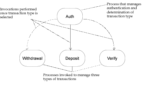
In this organization, the process labeled Auth is the most appropriate to act as the root process in the module, because it must always be present to begin new transactions. It would be possible to create the three child processes dynamically to manage transactions as they occur and then to destroy them; however, because only one transaction can occur at a time, there is no need to repeatedly incur the overhead associated with these mechanisms. The approach selected here is to have the Auth process create the three remaining processes as part of its own initialization and to continually reuse the same process instances as required to handle transactions requested by the user.
Medium Access System
Due to the fact that the system handles medium access for one packet at a time, there is no need for a variable number of identical processes to be created. However, several clearly distinct functional areas appear among the system’s activities.
- Acceptance and queueing of arriving messages.
- Transmission management for the earliest enqueued message.
- Monitoring the medium to determine correct times for transmission.
These three activities have some relationship to each other and must therefore be determined to operate asynchronously to form an appropriate decomposition of the system. If the system is idle (i.e., no packet is waiting to access the medium) then the queue-management process must inform the transmission management process immediately when a packet arrives. The transmission management process must also receive information from the medium-monitoring process whenever a collision occurs so that it can abort its transmission. In addition, the status of the medium’s usability must be available at all times to the transmission management process to decide when to initiate transmission attempts.
The medium-monitoring process must be running at all times—independently of the other processes—to accurately determine the times at which the medium becomes usable. The queue-management process may also be required to accept and enqueue many packets during the period required for the transmission process to successfully transmit just one packet; this queueing activity is a background task that has no effect on the transmission process except under one special circumstance noted above. The three activities therefore seem loosely coupled enough that they form a correct decomposition of the system into three asynchronously operating processes. This decomposition appears in the following figure.
Figure 129: Asynchronous Cooperating Process Decomposition for Medium Access System
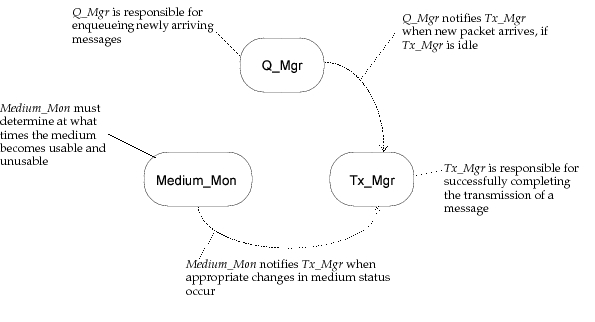
Any of the three processes could play the role of root. However, note that the Medium_Mon process must be present from the beginning to compute the usability of the medium which must be available at all times. If this process started later then it may not be known if the medium was busy in the early moments of the simulation, making it impossible to determine exactly at what time it should become usable for transmission. Also, the Q_Mgr process should be present at all times to handle the arrival of the first message. Only the Tx_Mgr process stands out as not being necessary in the initial moments because it can easily be created by the Q_Mgr after the first message arrives. Therefore, either Medium_Mon or Q_Mgr should be used as the module’s root process. The approach selected here is to use the Q_Mgr process as root and to create the Medium_Mon process immediately. Subsequently, the Tx_Mgr process will be created by Q_Mgr upon receipt of the first message for transmission.
Data Link Control System
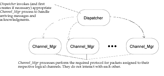
This system may involve the management of activities for a number of logical channels and this number may change over time. Furthermore, each logical channel can be considered to exist as a thread in the sense that it maintains state (e.g., the packet that has to be retransmitted) and requires activities to be continued over a period of time. Each logical channel can therefore be managed by an independent but identical process that is concerned only with the events that affect its channel.
A process is also required to accept new messages that are submitted for transmission and to receive acknowledgments from the remote destination because there is not a priori reason to route these directly to any particular process. Because all channel-management processes play a symmetric role, and because one process acts as a dispatcher of messages to the channel-management processes, it is a natural decision to appoint the dispatcher process as root. This process can in addition be responsible for creating the channel-management processes when a request is submitted for a channel that is not yet known. The organization of these processes is shown in the following figure.
Figure 130: Decomposition of Data Link Control into a Scalable Number of Dynamic Processes
Stage 3: Enumeration of Events
This stage of the design methodology is performed for each process defined in the process decomposition stage, rather than for the system as a whole. Generally, a process assumes some or all of the functions of the system in which it is located by performing actions and modifying state information in response to logical events. A logical event (as opposed to an ordinary simulation event) is an occurrence that requires the intervention of the process. The purpose of the event enumeration stage is to construct a complete list of the logical events that can affect the process of interest. The actual actions that are taken in response to these interrupts are the topic of a later stage in the methodology.
Identifying Logical Events
A process may be called upon to respond to an interrupt either directly by the Simulation Kernel or by another process within the same process hierarchy. In both cases, however, an event must first occur for the module that encompasses the process. The Simulation Kernel then chooses a process to receive the interrupt directly (the technique used to control which process is invoked directly is called interrupt steering and is described in detail in “Modeling Framework”). This process may in turn cause other processes to be invoked by calling the Kernel Procedure (KP) op_pro_invoke().
The first goal of this stage is simply to determine which logical events a process must be prepared to receive. The actual type of the corresponding interrupts or the way in which they are communicated is not important at this time; rather the causes of the interrupts and the sources from which they came must be identified. Each logical event should be assigned a descriptive name and placed in a list.
Logical events may be generated from three types of sources: (1) modules outside the local system; (2) other processes within the same module; (3) the process itself. Unfortunately, there is no general method for determining the interrupts of a process; however, the activities of the encompassing system as a whole and the interactions of the system are a good starting point. Not all of the interrupts that affect the encompassing system will necessarily affect the process of interest, but the irrelevant interrupts can easily be sorted out.
The developer should take into account interrupts that cause a direct invocation of other processes, provided that these processes directly or indirectly invoke the process of interest. In particular, other processes may generate interrupts for themselves and in handling those interrupts, invoke the process by calling op_pro_invoke(). Of course, self interrupts generated by the process for itself must also be identified, and the event of creation is also important for some processes (for root processes, this event occurs at the beginning of the simulation).
Determining Event Implementation Methods
The previous section identified the significance of the events; this section describes how logical events are implemented in the simulation model. The logical events that affect a process must manifest themselves as interrupts delivered to the process by the Simulation Kernel, or as invocations of the process by other processes within the same surrounding module. In both cases, an interrupt must have been delivered to one of the processes in the module for a logical event to occur.
While the significance of events varies widely and is dependent on the modeling application, Modeler supports only a small, finite set of interrupt types with which to implement these events. As a result, it is generally easy to select a correct type of interrupt to represent each logical event. The following table lists the logical events that are commonly encountered and the interrupt types that usually correspond to them.
Table 47: Common Logical Events and Usual Corresponding Interrupt Types
| Logical Event | Interrupt Type |
|---|---|
| Creation of process | begin simulation interrupt for root process; general for others |
| Expiration of timer | self interrupt |
| Receipt of message | stream interrupt |
| Receipt of command to do an action | remote interrupt or stream interrupt, depending on how command is represented |
| Change in status of other module | statistic interrupt or remote interrupt, depending on whether the other module is in the same node |
| Request to forward a packet to neighboring module | access interrupt |
| Change in operability status of a network-level object (node or link) | failure interrupt, recovery interrupt |
See “Modeling Framework” for a description of each interrupt type and possible uses.
Application to Examples
This section describes the application of the event enumeration stage to the four example systems described earlier.
Pay Telephone System
Most events can be easily extracted from the system definition, because most of the action descriptions depend on the occurrence of particular conditions. In the case of the pay telephone system, the events that are apparent include indications of actions taken by the user and signals sent by the network. In addition, note that the network provides a warning some time before the call must be disconnected, but no final disconnect signal; this event must therefore be generated internally (e.g., as a self interrupt). All the anticipated events of the process appear in the following table together with the interrupt types selected for their implementation.
Table 48: Logical Events for Pay Telephone Process
| Event Name | Event Description | Interrupt Type |
|---|---|---|
| User_Pickup | User takes handset off hook | statistic |
| User_Hangup | User replaces handset on hook | statistic |
| User_Add_Fare | User deposits money | stream |
| User_Tel_Num | User dials telephone number | stream |
| Net_Dial_Tone | Network provides dial tone | stream |
| Net_Connect | Network indicates call has gone through and whether call is toll-free | stream |
| Net_Fare_Low | Network warns that money has nearly run out | stream |
| Disconnect | Money has completely run out and call must be terminated | self |
Bank Teller System
The description of the bank teller system does not make the set of events as clear as in the case of the previous example. However, some of the events are implicit in the activities that are described. For example, if the customer can select between three transaction types, there must be an event which corresponds to the customer completing a selection. Also, insertion of the bank card and identification number correspond to two separate events. The account manager also generates events for authentication of the card and ID number, and approval of each transaction. In addition, an event must be generated to allow a customer to cancel a transaction in progress.
Because this system uses four processes, each process’ logical events must be enumerated separately. The following tables summarize the logical events expected by each process and the interrupt types that are used to implement them.
Table 49: Logical Events for Auth Process of Bank Teller System
| Event Name | Event Description | Interrupt Type |
|---|---|---|
| Cust_Card_Ins | Card has been inserted by customer | stream |
| Cust_ID_Entered | Customer has typed in personal identification number | stream |
| Cust_Trans_Sel | Customer has selected one of three transaction types | stream |
| Cust_Trans_Cancel | Customer has decided to cancel transaction (may happen at any time) | stream |
| Bank_Auth | Bank has authorized use of card based on ID number | stream |
| Bank_Reject | Bank has denied use of card based on ID number | stream |
| Cust_Trans_Over | Customer transaction has completed | invocation by corresponding child process |
Table 50: Logical Events for Withdrawal Process of Bank Teller System
| Event Name | Event Description | Interrupt Type |
|---|---|---|
| Cust_Amount_Entered | Customer has entered an amount needed for withdrawal transaction | stream |
| Bank_Trans_Approval | Bank has authorized completion of transaction | stream |
| Cust_Trans_Cancel | Customer has decided to cancel transaction (may happen at any time) | stream |
Table 51: Logical Events for Deposit Process of Bank Teller System
| Event Name | Event Description | Interrupt Type |
|---|---|---|
| Cust_Amount_Entered | Customer has entered an amount needed for deposit transaction | stream |
| Cust_Deposit_Inserted | Customer has inserted deposit documents through deposit door | stream |
| Cust_Trans_Cancel | Customer has decided to cancel transaction (may happen at any time) | stream |
Table 52: Logical Events for Verify Process of Bank Teller System
| Event Name | Event Description | Interrupt Type |
|---|---|---|
| Bank_Balance_Rcvd | Balance information has been received from bank | stream |
| Cust_Trans_Cancel | Customer has decided to cancel transaction (may happen at any time) | stream |
Medium Access System
This system relies on three processes, each of which is driven by a separate set of logical events. The root process is Q_Mgr, which is responsible for inserting newly arriving packets in the queue, where they will wait to be processed by the Tx_Mgr process. Q_Mgr’s logical events appear in the following table.
Table 53: Logical Events for Q_Mgr Process of Medium Access System
| Event Name | Event Description | Interrupt Type |
|---|---|---|
| Process_Create | Initial event provided to allow initialization of process | begin simulation |
| New_Message | A message has been submitted to the module for transmission onto the medium | stream |
The Medium_Mon process is responsible for determining the usability of the medium based on the activity of the recent past. It must therefore be notified each time that a change in the medium’s status occurs. In addition, the processes must be notified after the medium has been idle for Gap_Time seconds. Its logical events are listed in the following table.
Table 54: Logical Events for Medium_Mon Process of Medium Access System
| Event Name | Event Description | Interrupt Type |
|---|---|---|
| Process_Create | Initial event provided to allow initialization of process | invocation by Q_Mgr process |
| Busy_High | The medium’s status has changed from free to busy | statistic |
| Busy_Low | The medium’s status has changed from busy to free | statistic |
| Gap_Elapsed | The medium has been free for Gap_Time seconds, meaning that it has become usable for transmission | self |
The third and most complex process in this system is the Tx_Mgr process, which must manage, across repeated attempts if necessary, the transmission of the message onto the medium. This process may be invoked to begin transmission of a new message, or for various events that may occur during the transmission of a current message. Note that the process must use a self interrupt to know when its own transmission has completed so that it can begin another, if required. The complete set of logical events for Tx_Mgr is listed in the following table.
Table 55: Logical Events for Tx_Mgr Process of Medium Access System
| Event Name | Event Description | Interrupt Type |
|---|---|---|
| Process_Create | Initial event provided to allow initialization of process | invocation by Q_Mgr process |
| New_Message | New message has been submitted for transmission | invocation by Q_Mgr process |
| Medium_Usable | The medium has been free for at least the required gap time between messages, meaning that a transmission may begin | invocation by Medium_Mon process |
| Tx_Complete | Current transmission has completed without a collision | self |
| Tx_Collided | Current transmission overlapped with another transmission on the medium | statistic |
| Backoff_Elapsed | The random backoff period following a collision has elapsed, allowing a new transmission attempt | self |
Data Link Control System
This system uses two processes, with the root acting essentially as a dispatcher by routing arriving messages to the correct Channel_Mgr child process. The root process uses the model Dispatcher and responds to message arrivals from the message source and to acknowledgment messages returned from the remote site via the link. No events are generated internally, because dispatching is assumed to take no time to do and this is the only activity. The logical events of Dispatcher are listed in the following table.
Table 56: Logical Events for Dispatcher Process of Data Link Control System
| Event Name | Event Description | Interrupt Type |
|---|---|---|
| Process_Create | Initial event provided to allow initialization of process | begin simulation |
| Src_Message_Arrival | Message has arrived from traffic source to be queued for transmission with appropriate channel manager | stream |
| Link_Message_Arrival | An acknowledgment has been received from one of the channels, to be handed to the appropriate channel manager | stream |
Because the Dispatcher process has no other function than to create and invoke channel manager processes, the events in the table above also appear in the event table of the Channel_Mgr process. In addition, each Channel_Mgr must internally generate timer events to initiate retransmissions of unacknowledged messages, as listed in the following table.
Table 57: Logical Events for Channel_Mgr Process of Data Link Control System
| Event Name | Event Description | Interrupt Type |
|---|---|---|
| Process_Create | Initial event provided to allow initialization of process | invocation by Dispatcher process |
| Src_Message_Arrival | Message has arrived from traffic source to be queued for transmission | invocation by Dispatcher process |
| Link_Message_Arrival | An acknowledgment has been received from remote process | invocation by Dispatcher process |
| Ack_Timeout | Timer has expired while waiting for acknowledgment message from destination to support retransmission | self |
Stage 4: State-Level Decomposition of Processes
This stage of the methodology is performed for each process that has been defined within a system. State decomposition forms the basis of a state transition diagram (STD) that represents a Proto-C process.
Criteria for Defining States
The goal in this stage is to define a set of discrete states that will later be connected with transitions to form an STD. At this point only the states need be identified and if possible, the specific conditions for transitions should be examined in a later stage of development. The following guidelines should be used in selecting states:
- A state should correspond to a mode of the process in the sense that only specific sequences of events can bring the process into that state.
- A state is characterized by the fact that events are handled a particular way as a result of the process being located in that state.
- The combination of states should form a mutually exclusive, complementary set, such that the process always occupies exactly one of the states.
- A state should represent a “resting place” for a process, meaning that the process should be able to wait in the state for new interrupts to occur. This implies that the states that are defined in this step of the methodology should not be used simply to specify actions, and therefore are not the forced states of the process. Forced states are a convenient feature for graphically representing control-flow and are considered at a later stage.
Note that, as its name implies, a state represents part of the “memory” of a process because it reflects the path that the process has taken to reach it. However, not all of the memory of a process need be reflected by the state that it occupies, due to the fact that Proto-C provides state variables. Therefore, states can be used to represent logical modes of the system that are distinguished primarily by differences in the events that are expected and the way events are processed.
Application to Examples
Other than the criteria for state definition provided in the previous section, there is no general method that always yields an efficient set of states of a process. In some modeling problems, processes are already described as STDs in the system specification, making the selection of states straightforward. However, if this is not the case, the developer must try to select a set of states by analyzing the activities of the process and the events that occur.
When state selection is not obvious, one possible approach is to begin analysis with an initial state where the process would be located when it is created. Possible events that could occur while the process is in this state should then be considered one at a time; each event may lead to a new state that reflects its occurrence, unless a state already exists that represents a correct response to the event. In this way new states are defined, and event analysis can be performed again for the new states until there is no need to create additional states.
This section shows state decomposition by enumerating possible state sets for the processes of the four example systems defined earlier.
Pay Telephone System
This system is implemented as one process which must therefore respond to all possible events received by the system. These events were identified in the previous stage of the methodology. Examining the events suggests that the process follows a direct path through a predictable sequence of actions, as follows: (1) process is in idle state; (2) user picks up phone; (3) user deposits money; (4) network provides dial-tone; (5) user dials telephone number; (6) network establishes connection and indicates if fare is free; (7) conversation takes place; (8) user hangs up or money runs out; (9) call disconnected.
This sequence of actions does not represent the states of the process but provides a good starting point for discovering them. The key is to recall that states should represent intervals of time for the process between actions; this leads to the following set of states based on the above sequence:
Table 58: States for Pay Telephone Process
| State Name | State Description |
|---|---|
| Idle | Waiting for phone call to be initiated by a user. |
| Deposit_wait | Waiting for deposit to be made. |
| Tone_wait | Waiting for dial-tone to be provided by network so that user can begin dialing. |
| Dial_wait | Waiting for user to complete dialing so that connection can be established. |
| Connect_wait | Waiting for a connection to be established and for indication of whether call is toll-free. |
| Connect_estab | Connections has been established and conversation is ongoing; waiting for the user to terminate by hanging up or for the network to notify that money has almost run out. |
| Disc_ct_down | The warning has been received that money has nearly run out. A count down towards a disconnect is occurring; the user may avert this by depositing more coins. |
Bank Teller System
The bank teller system is composed of four processes for which states must be defined. The root process is called Auth and is responsible for the initial phases of a customer’s transaction with the teller. Specifically, Auth must obtain the user’s card and ID number and have them validated by the bank; then it must determine the type of transaction the user desires and start the correct child process to manage that transaction. These phases correspond to the states listed in the following table.
Table 59: States for Auth Process of Bank Teller System
| State Name | State Description |
|---|---|
| Idle | Waiting for customer to engage automatic bank teller by inserting card. |
| ID_wait | Waiting for customer to enter personal identification number. |
| Auth_wait | Waiting for authorization and account handle to return from bank. |
| Select_wait | Waiting for user to select transaction type. |
| Trans_compl_wait | Waiting for selected transaction to complete or to be canceled. |
The transaction management processes Deposit, Withdrawal, and Verify are simple processes that sequence a small number of events. Note that two approaches can be selected with regard to the creation of these processes: they may be created when the system initializes and be viewed as permanent resources, like subroutines in a program; or they may be created dynamically for each transaction and then destroyed when the transaction completes. In the former case, the processes would need an additional state which they would occupy while waiting for a transaction to begin. The second approach is selected in this case, thereby allowing the processes to assume that they are in the midst of handling a transaction. The states for the three processes are listed in the following tables.
Table 60: States for Withdrawal Process of Bank Teller System
| State Name | State Description |
|---|---|
| Amount_wait | Waiting for user to enter amount to be withdrawn from account. |
| Auth_wait | Waiting for bank to approve withdrawal of specified amount. |
Table 61: States for Deposit Process of Bank Teller System
| State Name | State Description |
|---|---|
| Amount_wait | Waiting for user to enter amount to be deposited to account. |
| Insert_wait | Waiting for customer to physically deposit envelope through deposit door. |
Table 62: States for Verify Process of Bank Teller System
| State Name | State Description |
|---|---|
| Balance_wait | Waiting for bank to acknowledge transaction and simultaneously return balance information. |
Medium Access System
The medium access system makes use of three asynchronously operating processes called Q_Mgr, Medium_Mon, and Tx_Mgr to control transmissions. After it is created, the Q_Mgr process expects only one type of logical event representing a message arrival. Each arriving message is processed independently of the previous ones, so the process has only one mode, as listed in the following table.
Table 63: States for Q_Mgr Process of Media Access Systems
| State Name | State Description |
|---|---|
| Message_wait | Waiting for a message to be submitted to the media access system. |
The Medium_Mon process is responsible for determining when the medium becomes usable and when it ceases to be usable. To do this, the process must time the silent periods on the medium and when a fixed silent interval has occurred, the medium can be declared to be usable. The logical events used in this decision process are the medium going busy, the medium going idle, and the silence interval elapsing, as described in the event enumeration stage of the methodology. These three events suggest a natural decomposition into three states, as listed in the following table.
Table 64: States for Medium_Mon Process of Media Access System
| State Name | State Description |
|---|---|
| Medium_usable | Medium is usable for new transmissions due to having been idle for at least Gap_Time seconds. |
| Medium_busy | Medium is currently busy (and therefore not usable for new transmission). |
| Gap_elapse_wait | Medium has changed from busy to free within last Gap_Time seconds and therefore is still not usable. |
Initially, the Tx_Mgr process has no messages to transmit and may later return to this condition after having completed transmissions if its input queue is empty. Therefore, a state to represent this idle mode is required. After a transmission begins, it can move through several phases: waiting for a usable medium; waiting to determine the status of a transmission; and if a collision has occurred, waiting for the random backoff timer to expire. These lead to the following state table:
Table 65: States for Tx_Mgr Process of Media Access System
| State Name | State Description |
|---|---|
| Idle | No transmissions are in progress; input queue is empty. |
| Medium_wait | Waiting for medium to become available, at which point a transmission can be initiated. |
| Tx_status_wait | Waiting to learn if transmission was successful or if a collision occurred. |
| Backoff_wait | A collision occurred and the backoff interval is currently counting down; waiting for this interval to complete so that the transmission may be reattempted. |
Data Link Control System
The multichannel data link control system uses a Dispatcher process to route arriving messages to the correct child process, which is of type Channel_Mgr. The routing is performed based on each message’s logical channel ID, independently of previous messages. The Dispatcher process has only one mode which is to wait for the next arriving message, process it and wait again. Its state table appears below.
Table 66: States for Dispatcher Process of Data Link Control System
| State Name | State Description |
|---|---|
| Message_wait | Waiting for a message to be submitted to the data link control system, either from the source or from the link. |
The Channel_Mgr process is more complex because each message that is handled follows a progression including a transmission phase, possible retransmissions, and an acknowledgment phase. In addition, queueing of new messages must be performed on an asynchronous basis (a second process might have been defined for this purpose as was done for the media access system; however, here this activity is simply performed as a background task in each state of the channel manager). A possible state table that supports these phases is shown below:
Table 67: States for Channel_Mgr Process of Data Link Control System
| State Name | State Description |
|---|---|
| Idle | No messages are available to transmit and no acknowledgments are pending; the process is waiting for a new message to arrive from the traffic source. |
| Ack_wait | A message has been transmitted and an acknowledgment is awaited; a timer may expire to indicate need for retransmission. |
Stage 5: Developing the State Transition Diagram
At this milestone, the states of each process have been defined. In addition, the set of logical events that require a response on the part of each process have been identified. The purpose of this stage is to combine these two sets of data to form the basic state transition diagram (STD).
Determining the Feasible Events of a State
For most process models, it is only possible for a subset of the logical events to occur while the process is located in a given state. This is generally due to the fact that the involvement of the process itself is required in the interactions that result in the event. For example, the authorization process of the Bank Teller System cannot expect the user to select a transaction type while it occupies the state where the card’s insertion is awaited, because the menu of possible transactions has not been presented yet.
To avoid including infeasible transitions in the STD, this methodology characterizes each event with respect to each state, using three categories: infeasible, suppressed, and feasible.
- Infeasible events are those that have no possibility of occurring due to the particular circumstance that the process finds itself in when occupying a given state, such as the Bank Teller System example mentioned above.
- Suppressed events are those that would have the physical possibility of occurring but that provide no useful information to the process. In the interest of efficiency and simplification, invocations of the process should be avoided for these state-event combinations. Various suppression mechanisms for interrupts are available and are described in other parts of this section. What is relevant at this stage in the methodology is not how to suppress these events, but simply to make the assumption that they will not occur. It is useful to sort them out now to support the work that will later be required in order actually implement their suppression.
- Feasible events are those that are not only possible to receive, but that the process may have a use for while occupying a particular state. These events form the basis for the definition of transitions in the STD.
The first step of this stage consists in constructing a table that maps logical events against states of the process. By systematically listing each logical event for each state, the developer can ensure that no important events will be ignored in the design of the STD (ignoring an event can later lead to simulation errors). For each state-event combination, one of the three feasibility categories above should be assigned. The following table provides an example of such a table for the case of the media access system’s Tx_Mgr process. The feasible events are highlighted because these are the principal ones of interest in the subsequent steps of this design stage.
Table 68: Feasible Events for States of Tx_Mgr Process
| State Name | Logical Event | Feasibility |
|---|---|---|
| Idle | New_Message | feasible |
| Idle | Medium_Usable | suppressed |
| Idle | Tx_Complete | infeasible |
| Idle | Tx_Collided | suppressed |
| Idle | Backoff_Elapsed | infeasible |
| Medium_wait | New_Message | suppressed |
| Medium_wait | Medium_Usable | feasible |
| Medium_wait | Tx_Complete | infeasible |
| Medium_wait | Tx_Collided | suppressed |
| Medium_wait | Backoff_Elapsed | infeasible |
| Tx_status_wait | New_Message | suppressed |
| Tx_status_wait | Medium_Usable | suppressed |
| Tx_status_wait | Tx_Complete | feasible |
| Tx_status_wait | Tx_Collided | feasible |
| Tx_status_wait | Backoff_Elapsed | infeasible |
| Backoff_wait | New_Message | suppressed |
| Backoff_wait | Medium_Usable | suppressed |
| Backoff_wait | Tx_Complete | infeasible |
| Backoff_wait | Tx_Collided | suppressed |
| Backoff_wait | Backoff_Elapsed | feasible |
Constructing an Event Response Table
Processes are driven by the occurrence of logical events. After a logical event is received, the process has the opportunity to carry out a sequence of five steps as follows:
- Actions may be performed by the exit executive statements of the unforced state that is currently occupied.
- The condition statements are evaluated for all of the outgoing transitions of the currently occupied state.
- Actions may be performed by the executive statement of the transition that is selected (i.e. the one that evaluates to a TRUE boolean value).
- The process follows the transition and occupies a (possibly) new state.
- Actions may be performed by the enter executives of the new state.
At this stage of model development, only unforced states of the STD have been considered. Forced states can be introduced later to improve model appearance, or consolidate redundantly specified actions; however, they do not alter the fundamental structure and timing of the model, which are provided by the unforced states and their transitions. Because transitions from unforced states always correspond to the occurrence of an event, the state-event combinations serve as a good starting point for defining the STDs transitions. Only feasible events need be considered because other events are assumed never to occur while in particular states.
The suggested approach to determining the STDs transitions is to generate a table, known as an event response table, that describes the process’ possible courses of action for each feasible state-event pair. The table lists every feasible state-event pair in the two left columns. For each such pair, at least one transition will be defined; in addition, it is possible that several transitions would be applicable provided that they are differentiated by additional requirements in their condition statements (recall that the conditions of all transitions departing from a state must be mutually exclusive). If the process must have the ability to transition differently or to do substantially different actions, based on the fulfillment of certain conditions at the time the event occurs, then these conditions must be characterized in the table; general “English-like” statements of these conditions should be entered in the third column of the table, called condition.
The next column, labeled Action, represents any activity that must be performed as a result of the transition taking place. Depending on the exact nature of the action, it could be implemented as part of the current state’s exit executive statements, as part of the transition’s executive, or in the next state’s enter executives; this issue is addressed in later stages and does not need to be specified in the table. Finally, the Next State column specifies which state the process should occupy next due to the occurrence of the event and the condition being true. The resulting table for the Tx_Mgr process of the Media Access System appears below.
Table 69: Event Response Table for Tx_Mgr Process
| Current State | Logical Event | Condition | Action | Next State |
|---|---|---|---|---|
| Idle | New_Message | medium is usable | begin transmission | Tx_status_wait |
| Idle | New_Message | medium is not usable | Medium_wait | |
| Medium_wait | Medium_Usable | begin transmission | Tx_status_wait | |
| Tx_status_wait | Tx_Complete | queue is empty | Idle | |
| Tx_status_wait | Tx_Complete | queue is not empty and medium is usable | begin transmission | Tx_status_wait |
| Tx_status_wait | Tx_Complete | queue is not empty and medium is not usable | Medium_wait | |
| Tx_status_wait | Tx_Collided | abort transmission; begin backoff | Backoff_wait | |
| Backoff_wait | Backoff_Elapsed | medium is usable | begin transmission | Tx_status_wait |
| Backoff_wait | Backoff_Elapsed | medium is not usable | Medium_wait |
Defining Transitions
This section introduces methods for defining transitions that will be used in the subsequent section where construction of the STD begins. No diagrams or tables need be generated from the information presented here.
As mentioned earlier, each logical event that is feasible in a given state must be handled by at least one outgoing transition of that state. One possible approach to defining the transitions of the STD is to consider each row of the event response table and to create a transition that matches its specifications. For example, consider a row defined as follows:
| Current State | Logical Event | Condition | Action | Next State |
|---|---|---|---|---|
| S0 | E | C | S1 |
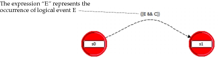
A transition could be defined between two states to express the following: if the current state is S0, and the logical event E occurs, and the condition C holds, then the process should move to occupy state S1. In Proto-C, as in the C and C++ languages, the operators && (two ampersand characters) and || (two vertical bars) are used to express the logical operations AND and OR, respectively. Therefore, the transition would appear as follows in a Proto-C diagram.
Figure 131: Representation of a Generic Transition in an STD
All transitions in an STD could be represented in this straightforward manner to encode all of the control-flow information in the event response table. However, there need not always be a one-to-one correspondence between logical events and transitions at a given state. There are two general forms that can be extracted from the event response table to express transition conditions:
-
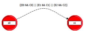
One transition may handle a union of multiple logical events – If in a given state of a process there are multiple feasible logical events, then it is possible for several of these events to cause a transfer to the same destination state. Proto-C supports the use of multiple transition objects to represent such situations; however, to reduce the complexity of STD, this methodology recommends using one transition with a condition statement that represents a union of the individual logical events and conditions. Therefore if three separate logical events E0, E1, and E2 cause a transfer to the same state, and each one has an associated condition C0, C1, and C2, respectively, then one transition can be defined, triggered by the condition (E0 && C0) || (E1 && C1) || (E2 && C2). This example is depicted below.
Figure 132: Transition Formed from the Union of Logical Events
-
Handling one logical event can be split among multiple transitions – The format of the table makes it clear that occurrences of the same logical event while in the same state may be differentiated by condition statements which are evaluated at the time of the event. For each condition statement, a different next state may be specified, thereby implicitly defining multiple transition objects. A situation of this type is depicted below for generic states, events, and conditions.
Current State Logical Event Condition Action Next State S0 E0 C0 None S1 S0 E0 C1 None S2 S0 E0 C2 None S3 Figure 133: Logical Event Handled by Multiple Transitions with Differing Conditions
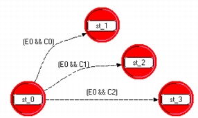
The Tx_Mgr process provides a good illustration of the use of conditions to subdivide the handling of one logical event. For instance, the table shows that in the Tx_status_wait state, the process may handle the receipt of a Tx_Complete event in three different ways, depending on the emptiness of the queue and the status of the medium.
Assembling the STD
After the event response table is defined, the STD can easily be assembled in the Process Editor. First, the states must be created and assigned names from the left column. The location of the states is not important, but depending on which transitions exist between them, certain arrangements can result in a cleaner looking diagram. Also, abbreviated state names are usually used because the states have only a small display window.
After the states have been placed, transitions may be drawn between them based on the methods presented in the previous section. When a transition is created, it has an empty condition statement, which is indicated graphically by a solid path (as opposed to a dashed path for transitions with non-empty conditions). Because variables have not been defined at this point and logical events are still treated conceptually (i.e., their specific method of implementation has not been decided), macros should be used to express the condition statements. The macros can be English-like text strings (no whitespace or special characters, except underscore) that provide descriptive labels for the transitions. The underlying definitions of the macros, which ultimately must implement the condition statements, can be provided in the process’ header block at a later time. The resulting STD for the Tx_Mgr process is shown in the following figure.
Figure 134: State Transition Diagram for Tx_Mgr Process
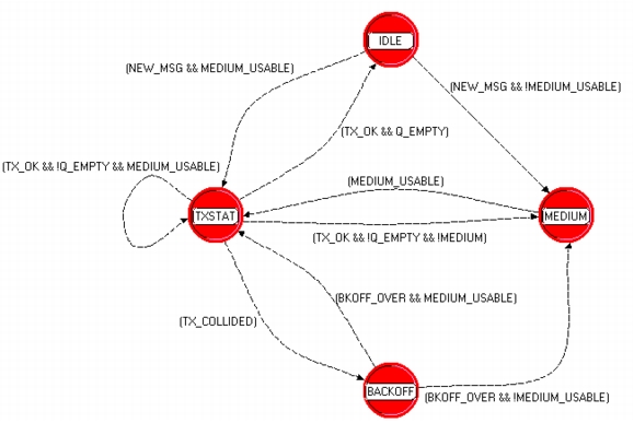
Table 70: Transition Condition Macros for Tx_Mgr STD
| Macro | Meaning |
|---|---|
| NEW_MSG | A new message has arrived |
| MEDIUM_USABLE | The medium is usable (i.e., it has been unused for Gap_Time seconds) |
| TX_OK | A transmission has completed successfully (no collisions) |
| Q_EMPTY | There are no messages waiting to begin the transmission process |
| TX_COLLIDED | The current transmission has experienced a collision |
| BKOFF_OVER | The backoff period has elapsed |
Note that even when there is only one outgoing transition from a state, as in the case of the state MEDIUM, that transition still has an associated condition. This condition is not strictly necessary because the process could assume that the correct event always occurs; however, including the condition allows the simulation to provide a warning if for some reason an unanticipated event occurs and the condition is false. This is preferable to falsely interpreting such an event.
Application to Examples
This STD stage of the methodology was applied to the Tx_Mgr process of the Media Access System in the previous sections to illustrate the construction of an event response table and the derivation of the STD. This section presents complete tables and STDs for the remaining example models that were defined earlier.
Pay Telephone System
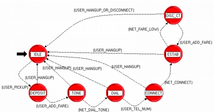
The STD for this process reflects the serial nature of the user’s progression through the various phases of call establishment. There is a loop between the Call_Estab and Disc_Ct_Down state, due to the fact that the phone user can always add change to continue the call. Also, every state has a transition back to the Idle state, reflecting the fact that the user may hang up the phone at any time. Most transitions are based on simple logical events; only the transition back to Idle from Disc_Ct_Down is driven by the union of two events (i.e., either can occur to cause this transition to be traversed).
Table 71: Event Response Table for Pay Telephone Process
| Current State | Logical Event | Condition | Action | Next State |
|---|---|---|---|---|
| Idle | User_Pickup | None | None | Deposit_wait |
| Deposit_wait | User_Hangup | None | None | Idle |
| Deposit_wait | User_Add_Fare | None | send indication of deposited amount to network | Tone_wait |
| Tone_wait | User_Hangup | None | refund deposit | Idle |
| Tone_wait | Net_Dial_Tone | None | None | Dial_wait |
| Dial_wait | User_Hangup | None | refund deposit | Idle |
| Dial_wait | User_Tel_Num | None | relay telephone number to network | Connect_wait |
| Connect_wait | User_Hangup | None | refund deposit; relay cancellation to network | Idle |
| Connect_wait | Net_Connect | None | None | Connect_Estab |
| Connect_Estab | User_Hangup | None | relay cancellation to network | Idle |
| Connect_Estab | Net_Fare_Low | None | start timer for disconnect | Disc_Ct_Down |
| Disc_Ct_Down | User_Hangup | None | relay cancellation to network | Idle |
| Disc_Ct_Down | Disconnect | None | relay cancellation to network | Idle |
| Disc_Ct_Down | User_Add_fare | None | send indication of deposited amount to network | Connect_Estab |
Figure 135: State Transition Diagram for Pay Telephone Process
Bank Teller System
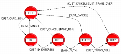
The Auth process of the Bank Teller System has a flow that strongly resembles that of the pay telephone system process described above. This could be expected because in both cases the process guides the user through a series of data entries to get to a phase where a transaction is established. This process also offers the possibility of cancellation by the user at any time, which is reflected by the transitions to the Idle state from all other states.
Table 72: Event Response Table for Auth Process of Bank Teller System
| Current State | Logical Event | Condition | Action | Next State |
|---|---|---|---|---|
| Idle | Cust_Card_Ins | None | prompt user for ID number | ID_wait |
| ID_wait | Cust_Id_Entered | None | send card info and ID to bank for authentication | Auth_wait |
| ID_wait | Cust_Trans_Cancel | None | return card | Idle |
| Auth_wait | Bank_Auth | None | prompt for transaction type | Select_wait |
| Auth_wait | Bank_Reject | None | return card | Idle |
| Auth_wait | Cust_Trans_Cancel | None | return card | Idle |
| Select_wait | Cust_Trans_Sel | None | invoke appropriate transaction process | Trans_compl_wait |
| Select_wait | Cust_Trans_Cancel | None | return card | Idle |
| Trans_compl_wait | Cust_Trans_Over | None | return card | Idle |
| Trans_compl_wait | Cust_Trans_Cancel | None | return card | Idle |
Figure 136: State Transition Diagram for Auth Process
The Withdrawal, Deposit, and Verify processes are very simple, requiring at most one action to be taken by the user to progress to their final state. Note that because these processes destroy themselves when receiving an event in their final state, departing transitions need not be defined. Also, the Cust_Trans_Cancel event always leads to destruction of the process, and therefore is not implemented by any transitions.
Table 73: Event Response Table for Withdrawal Process of Bank Teller System
| Current State | Logical Event | Condition | Action | Next State |
|---|---|---|---|---|
| Amount_wait | Cust_Amount_Entered | None | send request to bank | Auth_wait |
| Amount_wait | Cust_Trans_Cancel | None | notify parent that transaction is over; destroy process | none (process is destroyed) |
| Auth_wait | Bank_Trans_Approval | None | disburse cash; notify parent that transaction is over; destroy process |
none (process is destroyed) |
| Auth_wait | Cust_Trans_Cancel | None | notify parent that transaction is over; destroy process | none (process is destroyed) |
Figure 137: State Transition Diagram for Withdrawal Process
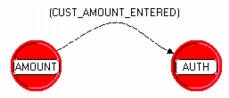
Table 74: Event Response Table for Deposit Process of Bank Teller System
| Current State | Logical Event | Condition | Action | Next State |
|---|---|---|---|---|
| Amount_wait | Cust_Amount_Entered | None | open deposit door | Insert_wait |
| Amount_wait | Cust_Trans_Cancel | None | notify parent that transaction is over; destroy process | none (process is destroyed) |
| Insert_wait | Cust_Deposit_Inserted | None | close deposit door; notify parent that transaction is over; destroy process | none (process is destroyed) |
| Insert_wait | Cust_Trans_Cancel | None | notify parent that transaction is over; destroy process | none (process is destroyed) |
Figure 138: State Transition Diagram for Deposit Process
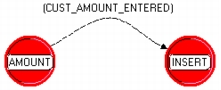
Table 75: Event Response Table for Verify Process of Bank Teller System
| Current State | Logical Event | Condition | Action | Next State |
|---|---|---|---|---|
| Balance_wait | Bank_Balance_Rcvd | None | display balance; notify parent that transaction is over; destroy process | none (process is destroyed) |
| Balance_wait | Cust_Trans_Cancel | None | notify parent that transaction is over; destroy process | none (process is destroyed) |
Figure 139: State Transition Diagram for Verify Process

Medium Access System
The Q_Mgr process is exceedingly simple, operating in a continuous one-state loop driven by message arrivals. At each arrival, a decision is made about whether to enqueue the message, or invoke the Tx_Mgr process; however the transition is always back to the same state.
Table 76: Event Response Table for Q_Mgr Process of Medium Access System
| Current State | Logical Event | Condition | Action | Next State |
|---|---|---|---|---|
| Message_wait | New_Message | Tx_Mgr is handling a message | Enqueue message | Message_wait |
| Message_wait | New_Message | Tx_Mgr is idle | Invoke Tx_Mgr to process message | Message_wait |
Figure 140: State Transition Diagram for Q_Mgr Process
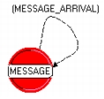
All transitions of the Medium_Mon process correspond to simple logical events. The Gap_Elapsed event has two separate conditions associated with it when the process is in the Gap_elapse_wait state, but in both cases, the next state is Medium_usable; therefore only one transition is necessary. The fact that different actions that are to be performed for each condition should not necessarily lead to the definition of multiple transitions. Even if transition executive statements are used to implement these actions, one statement can include conditional clauses (i.e., if statements) within it to handle each case appropriately.
Table 77: Event Response Table for Medium_Mon Process of Media Access System
| Current State | Logical Event | Condition | Action | Next State |
|---|---|---|---|---|
| Medium_usable | Busy_High | None | None | Medium_busy |
| Medium_busy | Busy_Low | None | start timer to measure gap | Gap_elapse_wait |
| Gap_elapse_wait | Busy_High | None | reset gap timer | Medium_busy |
| Gap_elapse_wait | Gap_Elapsed | Tx_Mgr is waiting for medium to become usable | notify Tx_Mgr of new status of medium | Medium_usable |
| Gap_elapse_wait | Gap_Elapsed | Tx_Mgr is not waiting for medium to become usable | None | Medium_usable |
Figure 141: State Transition Diagram for Medium_Mon Process
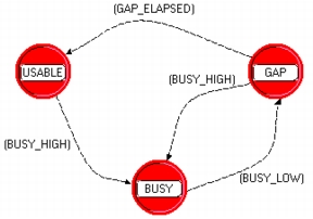
The Tx_Mgr process is not described in this section because it already appears as an example in the previous section.
Data Link Control System
The Dispatcher process receives messages from the link and from the traffic source. Messages from the link are acknowledgments sent by a destination process. Regardless of the received message type, the process always returns to the same state; this process is therefore another one-state loop, like the Q_Mgr of the Media Access System.
Table 78: Event Response Table for Dispatcher Process of Data Link Control System
| Current State | Logical Event | Condition | Action | Next State |
|---|---|---|---|---|
| Message_wait | Src_Message_Arrival | channel manager exists for this channel | invoke channel manager process and pass message | Message_wait |
| Message_wait | Src_Message_Arrival | channel manager does not exist for this channel | create channel manager and invoke with message | Message_wait |
| Message_wait | Ack_Arrival | channel manager exists for this channel | invoke channel manager process and pass acknowledgment | Message_wait |
| Message_wait | Ack_Arrival | channel manager does not exist for this channel | discard acknowledgment | Message_wait |
Figure 142: State Transition Diagram for Dispatcher Process
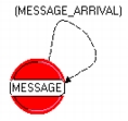
The Channel_Mgr process is simple in the sense that it has only two states; however there are six possible event-condition pairs departing from the Ack_wait state. The transition to the Idle state represents the logical union of two conditions, and the transition to the Ack_wait state represents four conditions. These conditions are not explicitly entered in the transition statements because they would be too long; instead a macro is used, as shown in the following diagram. Note that one of the transition’s condition statements could be replaced with the expression default because it is the complement of the other. However, this expression should only be used after thorough verification that all transition conditions are complementary; otherwise a missing transition that may have been overlooked in completing the event response table could be masked during simulation (i.e., no error can be reported).
Table 79: Event Response Table for Channel_Mgr Process of Data Link Control System
| Current State | Logical Event | Condition | Action | Next State |
|---|---|---|---|---|
| Idle | Src_Message_Arrival | None | start acknowledgment timer; begin transmission | Ack_wait |
| Ack_wait | Src_Message_Arrival | None | enqueue message for later transmission | Ack_wait |
| Ack_wait | Ack_Arrival | no messages enqueued | reset timer | Idle |
| Ack_wait | Ack_Arrival | at least one message enqueued | start acknowledgment timer; begin transmission | Ack_wait |
| Ack_wait | Ack_Timeout | fewer than Max_Attempts transmissions have been made | retransmit | Ack_wait |
| Ack_wait | Ack_Timeout | Max_Attempts transmissions have been made and at least one message enqueued | discard current message; start acknowledgment timer; transmit next message | Ack_wait |
| Ack_wait | Ack_Timeout | Max_Attempts transmissions have been made and no messages enqueued | discard current message | Idle |
Figure 143: State Transition Diagram for Channel_Mgr Process
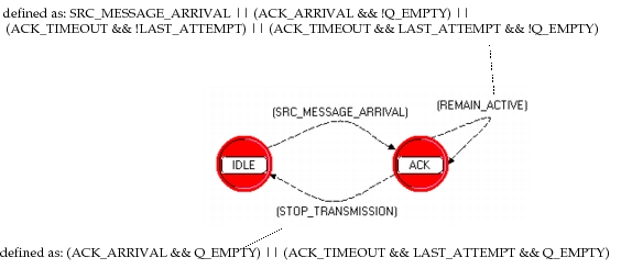
Stage 6: Specifying Process Actions
Process models do actions to modify their state memory, communicate with other modules, control their own timing, gather statistics, etc. Actions are performed by statements called executives, which respect a C syntax. Executives can make use of any C language operators and constructs, the process’ state, temporary, and global variables, and may include function calls to Simulation Kernel procedures.
Selecting Locations for Executive Statements to Represent Actions
Executive statements may be associated with states and with transitions. There are three types of locations in which executive statements can be placed to define the actions of a process:
- Exit executives – Any number of Proto-C statements may be inserted in this section of a state to model actions that take place immediately after receiving a new event, and before evaluating transitions.
- Transition executive – One line of Proto-C code may be associated with each transition to associate an action with a particular transfer of control from one state to another. Note that this executive can be a compound statement or a macro if a complex action is required. Also, function calls may be included within this statement.
- Enter executives – Any number of Proto-C statements may be inserted in this section of a state to model actions that take place after a transition, upon entering a new state.
These three sets of executives are executed without interruption in the order presented above whenever a process traverses a transition. The following figure shows this execution flow.
Figure 144: Executive Statements
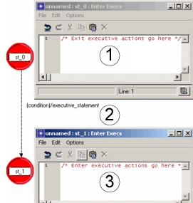
The following set of guidelines can be used in deciding which type of executive statements should implement actions:
-
Transition support – Complex transition requirements sometimes make it difficult to develop boolean expressions for the associated conditions. This is particularly true if transition conditions depend upon results of a multistep algorithm. Because transition conditions are evaluated after the completion of the exit executives of a transition’s source state, these executives provide an appropriate location to place computations that support the evaluation of outgoing transitions.
A typical example of transition support in the exit executives is shown below. In this case, a stream interrupt has been received due to the arrival of a packet, and several outgoing transitions are possible. The conditions of the transition depend on values to be extracted from the packet. To evaluate the transition conditions without using the exit executives of the source state would require that the condition statement be a procedure call where values would be extracted from the packet and computations would be performed to return a boolean result. This type of solution can be cumbersome and may require coordination between procedures representing alternative conditions.
Figure 145: Transition Support Statements in Exit Executives
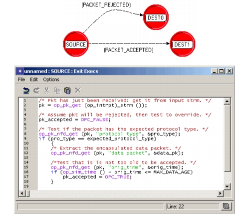
-
Actions not directly related to transition conditions – When an event occurs, the process may be required to do a number of actions that are either unconditional, or that depend upon conditions that are not identical to those of any of the outgoing transitions of the current state. In such cases, the transition executives are not the correct location to implement these actions. In addition, because the actions are not related to the destination state that will eventually be chosen, the enter executives of the destination states are not correct either. The exit executives of the current state do provide the correct context for these actions because they are executed prior to evaluating the transitions.
As an example of this type of situation, consider a process that allocates jobs to servers. The process has two states, one representing the case where servers are available, and the other the case where all servers are busy. When a new job arrives, say in the form of a packet, the process must enqueue the job with all other jobs that are waiting for service; then if a server is available, it may invoke the server to begin processing the job. If the invoked server happens to be the last one available, then the process must move to the state that indicates saturation of servers; otherwise it can self-transition back to the state that indicates servers are still available.
Figure 146: Use of Exit Executives to Implement Actions Independent of Transitions
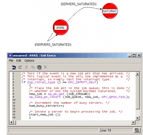
Note that conditional actions may be implemented within the exit executives as well by making use of C language
ifstatements. For example, if the queue had a limited job-holding capacity, the process could test within the exit executives that there is sufficient room in the queue, prior to attempting to insert the job packet. -
Actions and transitions dependent on identical conditions – Certain actions performed in response to an event are conditional on additional prerequisites, as explained earlier. This is also true of transitions. In cases where exactly the same conditions are required for a transition and for an action, the action may be implemented in the executive statement of the transition, provided that: (1) the action is not required to complete before the transitions are evaluated; and (2) the action is not also performed for all other transitions sharing the same destination state; and (3) the action is conveniently represented in the single line provided for a transition executive.
The principal advantage of implementing actions in transition executives, when possible, is that the action and the transition are closely associated and that this association is visible in the process model diagram. The tight coupling of the action and the transition show clearly that the action is not associated solely with the source state or with the destination state, but with the specific transfer of control between the two. A second advantage, though less important, is that the condition shared by the action and the transition need not be evaluated twice; depending on the complexity of the condition, this could result in significant performance differences. Finally, a third advantage of this technique is that expressing the condition in only one location simplifies maintenance of the process’ logic.
Consider as an example the Tx_Mgr process defined elsewhere. Suppose that as part of its performance monitoring requirements, the process must keep track of the number of occasions on which arriving messages are immediately processed, rather than having to wait for the medium to become available. The submission of a new message corresponds to the two transitions departing from the Idle state. However, only the transition leading to the Tx_status_wait state corresponds to the specific condition of interest, which is the immediate usability of the medium. Because there is no requirement for the counter to be updated prior to evaluation of transition conditions, this action may be performed in the transition’s executive statement, as shown in the following STD fragment.
Figure 147: Use of Transition Executive to Implement an Action
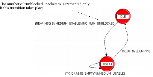
-
Actions associated with entry into a state – Actions that are performed each time that a state is entered, regardless of which transition was traversed to arrive there, should be associated directly with that state rather than any of the transitions or source states. The correct location for such actions to be implemented is the enter executives of the state of interest.
The Tx_Mgr model provides a good example for this case as well. The Tx_status_wait state is responsible for determining if an ongoing transmission is successful or affected by a collision. Suppose that to detect the end of its own transmission, the process sets a timer when the transmission begins; the duration of the timer is exactly equal to the transmission time of the packet. The Tx_status_wait state is entered via transitions from several states, including a transition from itself. However, regardless of the reason for entering this state (e.g., retransmission, first-time transmission without waiting, first-time transmission having waited, etc.), the action of setting the transmission timer must always be performed. Therefore, the enter executives of the Tx_status_wait state provide an appropriate location for this action. The following figure depicts use of the enter executives in this example.
Figure 148: Use of Enter Executives for Actions Associated Exclusively with State Entry
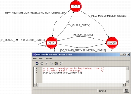
Note that there are ambiguous cases, where one transition leads into a state and there is an action to be performed that can be associated with arrival into that state. In such cases, the transition executive and the enter executives of the state provide equally valid locations for this action to be implemented.
-
Actions associated with a non-singular subset of transitions – If an action is to be performed subject to the union of the conditions of more than one outgoing transition, but not the complete set of outgoing transitions, then the exit executives do not provide a good location to implement the action. This is due to the fact that the exit executives contain logic that is common to all outgoing transitions. Similarly, if a subset (of more than one) of the transitions arriving at a state correspond to the performance of an action, the enter executives of that state should not be used to implement the action. However, there are two other options for each of these cases: (1) if the action can be represented in a compact form and there are a relatively small number of transitions, then the executive statements of these transitions can be used to represent the action; (2) a forced state can be created to implement the action in its enter executives and the applicable transitions can be rerouted to pass through that state.
Implementing the actions in the transitions’ executives is the most straightforward solution to this problem. In addition, this has the advantages of introducing no additional unforced states. However, because the action is implemented in several locations (i.e., on each transition in the subset), maintaining it may require additional effort. Therefore, if this solution is chosen, the action should always be implemented by means of a macro or function call, so that all changes that may need to be made can be made in one place. The following diagrams illustrate the use of the transition executive approach for both outgoing and incoming transitions.
Figure 149: Subset of Outgoing Transitions Doing the Same Action As Transition Executives
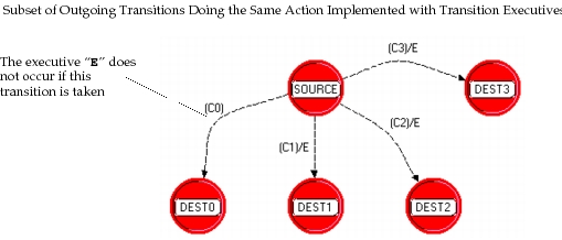
Figure 150: Subset of Incoming Transitions Doing the Same Action As Transition Executives
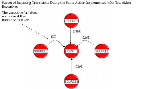
Using a forced state to contain the action can be useful if the action’s implementation is complex. This approach presents the advantage that the executive statements are located in only one place. However, it has the disadvantage that it requires an additional element in the STD. Also, in the outgoing transition case, the condition statements must be duplicated, first to form their union on the transition to the forced state, and then to separate control flow to the multiple destination states. The following figures show the use of a forced state for both cases:
Figure 151: Subset of Outgoing Transitions Doing the Same Action Implemented by Redirection
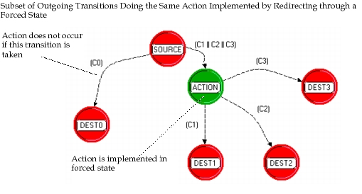
Figure 152: Subset of Incoming Transitions Doing the Same Action Implemented by Redirection
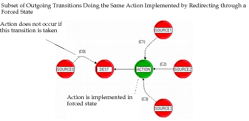
Developing Action Statements
To simulate a process, actions must be specified in a form that can be executed within the discrete event simulation environment. Specifying actions on a level that can be executed is referred to as implementation of the actions. Executive statements that constitute an action’s implementation are required to obey the syntax of the C language, and may make use of any of its operators and constructs. In addition, executive statements are often based on a library of C functions known as Kernel Procedures or KPs.
Before proceeding to actual implementation, it is useful to develop a logical specification for a process’ actions. A logical specification is concerned with the behavior, timing, and effects of an action, but not with the details of how the action is actually carried out. By first developing the process’ actions on an abstract level, the developer may more easily manipulate the action statements, notice commonality between them, and apply the placement guidelines formulated in the previous section.
Determining the Logical Actions of a Process
In an earlier section pertaining to this development methodology, an event-response table was generated. One of the columns of this table contained actions that would be performed as a result of a logical event taking place and a condition being met. These actions are logical actions of the process because they presented in an abstract manner without implementation details.
During the development stage where the event-response table is constructed, the main objective is to outline the control flow of the process by specifying the transitions between states. Actions are included in the table because they often depend on the same events and conditions as transitions and therefore can easily be captured simultaneously. Therefore, at this stage of development, the event response table should be revisited as a useful starting point for determining the process’ logical actions. Actions taken from the table should be given consistent high-level names and placed within the process model according to the guidelines of the previous section. Note that the structure of the table facilitates the application of these guidelines as summarized by the following set of statements:
- An action should be placed in the exit executives of a state if it appears in all rows for which that state occupies the “Current State” column, because it therefore applies to all transitions.
- An action should be placed in the enter executives of a state if it appears in each row that identifies the state as the destination of a transition (i.e., the “Next State” column contains the state’s name).
- An action should be placed in the executive statements of the transitions that share the same rows, if neither of the two previous criteria are satisfied.
It is appropriate that the process’ event response table should serve as a basis for specifying actions because actions are performed in reaction to the occurrence of logical events. However, the event-response table may not always include a complete specification of all actions that a process is required to do. A discrepancy may arise from the fact that the combinations of events and conditions that appear in the table do not correspond directly to the conditions under which certain actions are performed. As a result, certain action specifications may be overlooked. However, because the transitions leaving each state are required to form a complementary set (at least one must be true), it should be possible to associate all actions with one or more of the conditions; in the case where a condition supersedes the condition required for an action, the action can be considered to incorporate an additional restrictive clause (e.g., an “if” statement); in the case where an action is dependent on a condition that overlaps several conditions associated with transitions, the action can simply appear in multiple rows. Therefore all actions can and should be represented within the event-response table.
The following subsection of an event-response table lists the specification of actions that are subject to conditions that do not identically match those of the transitions. The action “A” partially overlaps two transitions and is subject to the condition (E0 && C0 && C0’) || (E1 && C1 && C1’); the action “A2” is supersetted by the third transition and depends on the condition (E2 && C2 && C2’).
| Current State | Logical Event | Condition | Action | Next State |
|---|---|---|---|---|
| S0 | E0 | C0 | if C0’ then A | S1 |
| S0 | E1 | C1 | if C1’ then A | S1 |
| S0 | E2 | C2 | if C2’ then A2 | S1 |
Logical actions should be entered into the process model executive areas simply as high-level names. Later, during the implementation phase, these macros can be fully defined within the header block, or replaced in-line by actual implementation statements. The action statements of the Tx_Mgr process (described as part of the Media Access System example) are shown as an example in the following figure.
Figure 153: Logical Actions of the Tx_Mgr Process
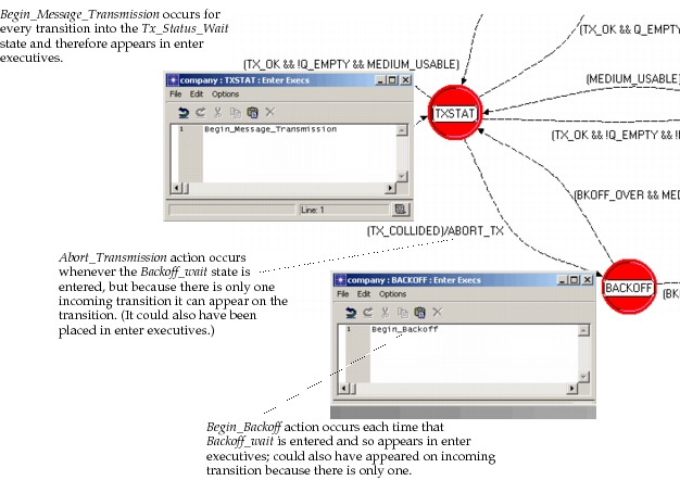
Implementation of Actions
For a process to become executable as part of a simulation, each of the logical actions associated with its states and transitions must be expressed in a form that can be understood by the discrete event simulation environment. Generally, each logical action is decomposed into a series of statements. The statements may appear directly in the location where the action was placed originally; they may constitute a macro defined in the process’ header block; or they may be placed in a function that is called from the location of the action.
Regardless of their placement, implementation statements must respect the syntax of the C language. Many implementation statements consist of calls to KPs defined in the Simulation Kernel. Other common statements are ordinary C language operations such as variable assignments, if statements, or for loops. There are no general guidelines for designing the content of implementation statements because this depends to a significant extent on the nature of the application. Some common examples of the implementation of actions are provided in Chapter 4 “Modeling Framework” on page 80, organized according to the type of event that the actions are designed to respond to. In addition, the “Discrete Event Simulation API” provides general descriptions of how to use the capabilities provided by KPs and numerous examples of process action statements.
Implementing Event Suppression
Implementation of logical actions that are described at a high level often entails the specification of accompanying peripheral actions, such as updating state variables or reporting statistics. One particular set of peripheral actions is required in most models to support the correct operation of the STDs transitions by ensuring that only the feasible events of a process can occur in each state.
To develop the event-response table of a process, the notion of event feasibility was introduced earlier in this section, whereby each logical event of a process was categorized as feasible, infeasible, or suppressed with respect to each state. Suppressed events are those that could normally occur while the process occupies a particular state, but for which special disabling measures have been taken. Because the Simulation Kernel has no knowledge of which events should be withheld, it is the responsibility of a process to autonomously implement event suppression at the correct times.
The most straightforward and systematic way to implement event suppression is to place a statement in the enter executives of each state to specifically disable events that should be suppressed while the process occupies that state; in the exit executives one statement can be placed to enable all events. Because the same logical events are likely to be suppressed in several different states, it is usually most efficient to use macro expressions to do these actions and to later define their exact implementation in the header block. An illustration of this approach appears below for the Tx_Mgr example process.
Figure 154: Event Suppression Statements for Tx_Mgr Process
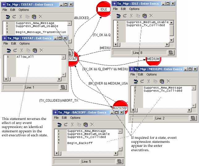
The underlying mechanism that is used to implement the event suppression macros is often based on the KPs op_intrpt_disable() and op_intrpt_enable(). See “Modeling Framework” for more information about event suppression provided by the Kernel. In situations where multiple processes generate logical events for each other via invocation, event suppression may be controlled by semaphores. For example, Tx_Mgr receives New_Message events when the Q_Mgr process invokes it as a result of having received a new message; suppressing this event for Tx_Mgr therefore should be implemented by notifying the Q_Mgr process rather than using a Kernel service. A semaphore residing in memory shared by the two processes would provide appropriate support for this mechanism.
Implementing Hierarchical Process Invocation
One of the approaches proposed by this methodology suggests the use of hierarchically related dynamic processes to reduce the complexity of individual models. The Bank Teller System provides an applied example of this technique where the process Auth uses the child processes Withdrawal, Deposit, and Verify to do tasks.
When it is appropriate for a child and parent process to execute asynchronously, then the simple use of the KP op_pro_invoke() provides the necessary functionality. As soon as the child process completes an invocation, the parent process can resume execution. However, when the desired timing relationship is that the parent process should not resume execution until the child process has reached a certain state, then additional mechanisms are required. Because it may take an arbitrary amount of time and events for the child process to achieve completion of the task, it generally bears the responsibility for notifying the parent process when it may resume. The mechanism for this notification is usually also the KP op_pro_invoke() because it has an immediate effect. If non-immediate notification is sufficient, then the semaphores implemented in shared memory between the processes may be used as well. The following diagram provides an example of the Proto-C statements that may be used to implement this type of configuration, which is referred to as a synchronous hierarchical execution of the child process, because it does not allow the parent process to execute asynchronously to the child process.
Figure 155: Synchronous Hierarchical Execution of Withdrawal Process by Auth Process
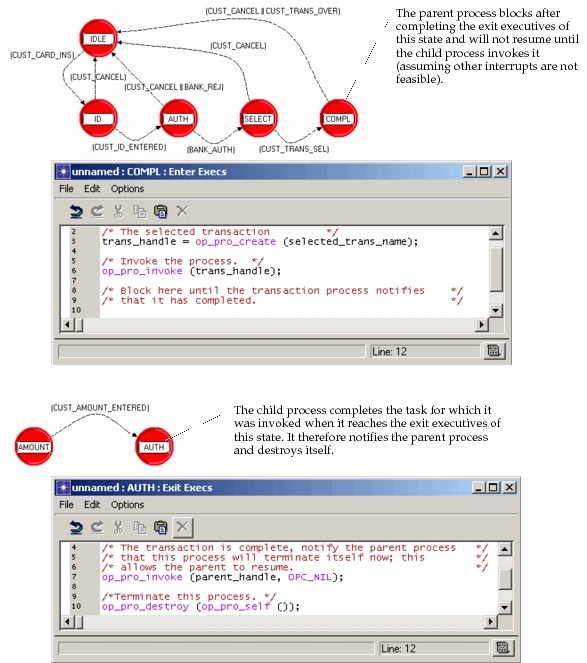
Stage 7: Selecting an Initial State
An earlier section presents four techniques for STD initialization using the various combinations of initial states and begin simulation interrupts. While all four methods are possible and may be useful under certain circumstances, this methodology suggests that only the two techniques that require begin simulation interrupts should be used. The advantages of requiring a begin simulation interrupt are the following:
- Because begin simulation interrupts happen before all other types interrupts, the process can position itself in a standard manner for the handling of all mainstream interrupts. Namely, when a mainstream interrupt occurs, the process is always poised to begin the exit executive statements of an unforced state.
- Processes can be depended upon to have completed all initialization activities by the time the first mainstream events occur. This may be important if processes depend on each other being in an initialized state (e.g., processes that share memory usually depend on one process to set the memory contents to meaningful values before others attempt to access it).
- By standardizing on use of begin simulation interrupts, it is always known that queue and processor objects should be configured to enable delivery of these interrupts (coordination with regard to this issue between the node and process domains is not otherwise enforced).
The two possibilities that remain are for the initial state to be forced or unforced. Because the objective is to have the first mainstream interrupt be handled in the exact same manner as in steady-state, use of an unforced state implies use of one of the principal states of the STD, already defined during earlier development. An additional unforced state should not be created, for it would require special transitions to handle the occurrence of the first mainstream interrupts, and this unnecessarily adds complexity and redundancy to the model. However, in most cases, principal states of the STD are designed to be entered repeatedly by the process as new events occur. Therefore, to avoid repeated execution of initialization actions throughout the life of a process, the initial state should be unforced only if the process is not required to do any initialization actions.
Figure 156: Use of Unforced State as Initial State
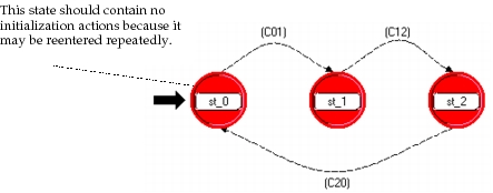
The second possibility is to create a new forced state to act as the initial state. Because a begin simulation interrupt is expected, the process can do initializations and immediately position itself in one of the unforced states of the module. In general, each process model has a particular unforced state that makes sense to use for this purpose, but this can only be determined based on the significance assigned to each state. Note in addition, that the enter executives of this unforced state will be executed at initialization time; therefore any actions therein that should not be performed at initialization time should be moved to the appropriate incoming transitions.
Figure 157: Use of Forced State as Initial State
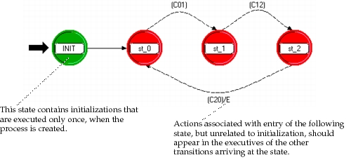
Application to Examples
The following table lists the choices made with regard to the initial state for each of the example processes described in this section.
Table 80: Initial States Selected for Example Processes
| Process | Strategy | Reason for Selection |
|---|---|---|
| Pay_Phone | use Idle as initial state | Idle is the natural initial position of the process because no transaction is assumed to be in progress at time zero; no initialization statements are required that do not also need to be executed each time that Idle is reentered |
| Auth | use of Idle as initial state | same as above |
| Deposit | use of Amount_wait as initial state | Amount_wait state is never re-entered because process is destroyed |
| Withdrawal | use of Amount_wait as initial state | Amount_wait state is never re-entered because process is destroyed |
| Verify | use of Balance_wait as Initial state | Balance_wait state is never re-entered because process is destroyed |
| Q_Mgr | use of new, forced Init state | one-time only initializations are required (e.g., creation of other processes) and only other state is reentered |
| Tx_Mgr | use of new, forced Init state | one-time only initializations may be needed, and other states may be entered multiple times |
| Medium_Mon | use of new, forced Init state | same as above |
| Dispatcher | use of new, forced Init state | one-time only initializations are required (e.g., creation of process list) and only other state is reentered |
| Channel_Mgr | use of new, forced Init state | one-time only initializations may be needed, and other states may be entered multiple times |
Note that for several of the processes, the solution requiring a new, forced initial state was selected to allow the possibility of later specifying initialization actions. This is due to the fact that other states that are candidates for being the initial state may be entered multiple times by the process.