External System Editor Operations
This section contains procedures for using the External System Editor to create ESD models, including:
Creating ESD Models
Procedure 211: Creating an External System Definition
-
Choose File > New, select External System Definition from the pull-down list, and press OK.
Result: An empty External System Editor opens.
-
Click in the Simulator Description field and select an ESD file from the list.
This list includes all available files defining how to build a cosimulation (
.sdfiles). -
Define any esys interfaces needed by the external simulator, as described in Defining Esys Interfaces.
-
Add to the Comments field (the large field at the top of the editor window) any information a user may need about how to use the ESD model.
-
Save the model.
Defining Esys Interfaces
Esys interfaces are defined in a table. In this table, each row represents a single esys or vector interface and each column represents an interface attribute.
Figure 208: Interface Table
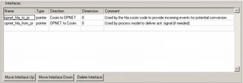
Procedure 212: Defining esys Interfaces
-
Open the ESD model for which you want to define interfaces.
-
For each interface, do the following:
2.1 Click in the Name cell of the first empty row and enter a name for the interface.
2.2 Click on the Type cell for the interface and select a data type from the list.
2.3 Click on the Direction cell for the interface and select the data flow direction that the interface should support.
2.4 If this is a vector interface, click in the Dimension cell for the interface and enter the number of values in the vector. (For a standard esys interface, leave the Dimension attribute set to 0.)
2.5 Click in the Comment cell for the interface and enter a description of the interface.
-
If necessary, use the buttons below the interface table to delete interfaces or change their order. Each button affects the selected interface row.