Switching Elements
Switching elements in the network topology neither generate nor sink traffic. Instead, they retain connection information related to the network and switch incoming packets through a fabric. The atm_cloud node models aggregated switching elements, which would typically be a service provider’s network. You can specify values for the loss and delay across the aggregation. The models are:
atm_<switch_name>- atm_cloud
The following figure shows the internal architecture of an ATM switch.
Figure 95: ATM Switch Architecture
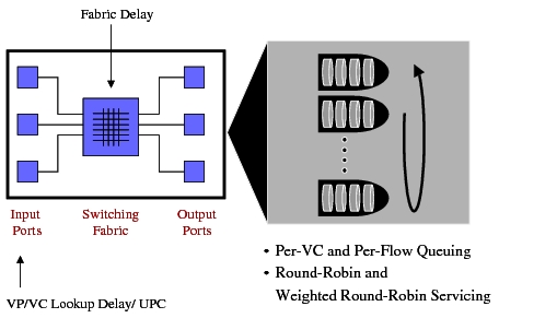
Notice that the input ports of a switch perform UPC, if enabled, and introduce a VP/VC lookup delay for every cell. Every cell then experiences a fabric delay, as specified by the switching speed. Finally, the output ports perform buffer management; each port has an independent set of buffers that are managed separately. The buffers can be categorized on a per-VC or per-class basis.
Setting up Multiple Calls from a Source Node
You can set up calls for the following:
ATM Uni-Source
The ATM Uni-Source can be configured with multiple calls as shown below.
Figure 96: Setting Up Multiple Calls from ATM Uni-source
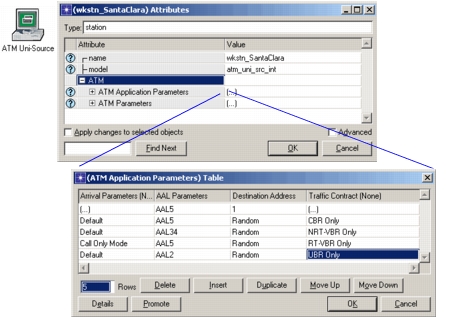
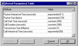
Each row in the ATM Application Parameters table represents one call. Each call can be repeated as many times as required during the simulation. This can be done by setting the Arrival Parameters as shown below:
Figure 97: Arrival Parameters Table
Call Only Mode: By setting the ATM Application Parameters or the Arrival Parameters to Call Only Mode, you can quickly perform capacity planning on your network. In Call Only Mode, only signaling data is generated; no actual data traffic is generated. By setting the incoming calls to Call Only Mode, bandwidth is reserved on the ports and SPVX, if any. In this manner, you can determine the amount of bandwidth used on the links and the amount that is free. Statistics such as the Call Blocking Ratio can be collected to view the number of calls being blocked.
ATM Uni-Clients
The ATM Uni-Client can also be configured with multiple calls. This is done by configuring multiple concurrent application sessions. Each session is represented as one call.
ATM Workstations
The incoming IP traffic can be characterized into different circuits based on a number of options, such as ToS or Destination Address. Each characteristic can then be assigned to a different connection, so that all traffic belonging to that characteristic flows over the specified connection to the destination.