Troubleshooting Multicast VPNs
This section offers suggestions for analyzing and troubleshooting multicast VPNs configured on Huawei devices. The example discussed in the procedures below is a multicast VPN configuration (VPN RED) with three PEs and three CEs. Tunnel binding is MTunnel0. The MDT share group is 239.1.1.1. The MDT switch group is 225.2.2.0/28, with a threshold of 100Kbps.
Note: Some limitations exist for showing multicast routes. First, because Show Routes cannot specify VRFs, for a multicast VPN you can only show client trees from a client node. If you are showing routes inside the core or on a PE, only the mVPN groups are shown. In other words, this functionality lacks the ability to select context as for unicast routes. Additionally, Show Routes will only be valid for the first execution after each flow analysis. To obtain another valid result, you must run another flow analysis first.
Verify Connectivity in a Unicast VPN
mVPN needs unicast VPN in order to work. The following procedure helps to verify the connectivity.
Procedure 58: Verify Connectivity in a Unicast VPN
-
Run a flow analysis in the scenario.
-
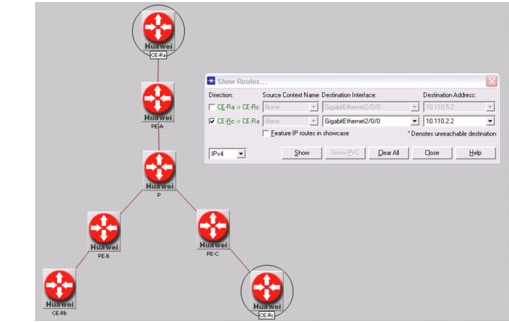
Show routes between the CEs. An example is shown below. Green or black text of the device names indicate connectivity
Figure 248: Show Routes Between CEs
-
Alternatively, show routes between the PEs with the VRF selected as the Source Context, as shown below.
Figure 249: Show Routes Between PEs
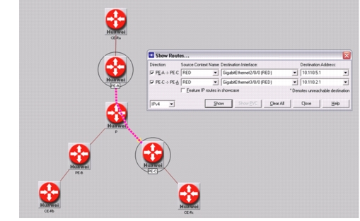
Note: If the CEs or the VRFs are not reachable, troubleshoot unicast VPN configuration.
End of Procedure 58
Verify Proper Configuration of a Multicast VPN
Once connectivity is established and verified across the unicast VPN, you may need to verify that multicast VPNs are configured correctly in the network. Use the following troubleshooting tips to do so.
Procedure 59: Verify Proper Configuration of a Multicast VPN
-
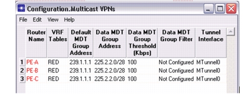
Check the mVPN configuration in the Configuration.Multicast VPNs report, shown below, which shows the mVPN configuration on each PE.
Figure 250: View mVPN Configurations on PEs
-
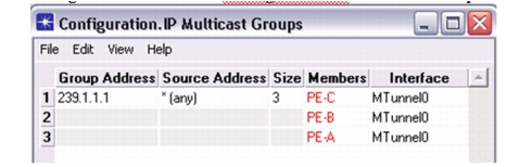
Even without traffic, PE routers will join the share-MDT tree using the address configured. Check this in the Configuration.IP Multicast Groups report, shown below.
Figure 251: View PE Routers in Multicast Groups
-
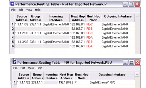
Next, check the creation of the share-MDT tree by showing the Performance.Routing Table - PIM on each PE or P router. In the tables shown below, note the tree created between all PEs inside the core.
Figure 252: View Multicast Tree for PEs
-
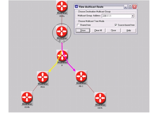
Alternatively, you can visualize the share-MDT tree from any PE, as shown below.
Figure 253: Visualize Multicast Routes
End of Procedure 59
Create and Test Traffic Flows for a Multicast VPN
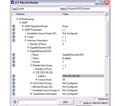
If you have verified both connectivity and configuration of your multicast VPN, you can create user traffic flows. Since you are not importing actual hosts that receive the multicast traffic, you will configure IGMP membership on the CE router and also create a multicast flow that sources from another CE router. The following example assumes that some attached host from CE-Ra is sending a multicast to group address 235.235.235.235, and some attached host to CE-Rb at the subnet of its GE2/0/0 interface wants to receive this traffic. Use the following procedure to configure group membership.
Procedure 60: Create and Test Traffic Flows for a Multicast VPN
-
Configure IGMP membership in the following attribute on a CE, in this case CE-Rb.
Figure 254: Configure Group Membership
-
Create a multicast flow from another CE, in this case CE-Ra.
-
Select CE-Ra, and choose Traffic > Create Traffic Flows > IP Multicast…
-
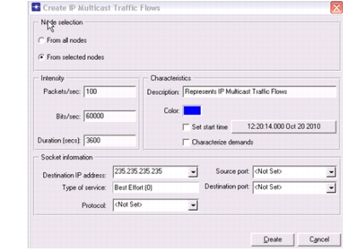
Fill in the Destination Address and change other attributes, if needed. Here we change the Bits/sec to 60000 to create a 60kbps flow.
Figure 255: Create IP Traffic Flow
-
-
After creation of the traffic flow, choose View > Demands > Show All. You will see a blue arrow that represents the traffic you just created.
Figure 256: Show All Demands

-
Run Flow Analysis. As the traffic has only 60Kbps, which is less than the configured switch MDT threshold, you can expect it to use the share-MDT in the core. You will verify this in the steps below.
-
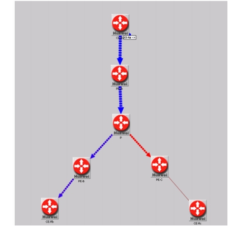
Right-click on the traffic flow, and select Show Routes (Flow Analysis). You will see the route taken by the traffic. Notice that the traffic splits at P, although there is no traffic beyond PE-C. This indicates the use of the share-MDT tree, which spans all PEs. The traffic split from P to PE-C is shown in red, which indicates there is no receiver for this path.
Figure 257: Show Routes (Flow Analysis)
-
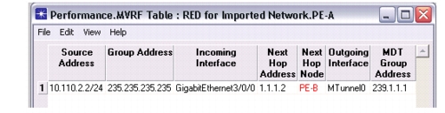
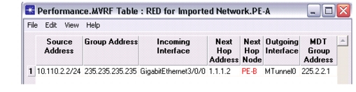
You can see more information from the Performance.MVRF Table on PE-A. This indicates that group address 235.235.235.235 will exit MTunnel0 into the mVPN domain and will use 239.1.1.1 in the core, which is the default MDT.
Figure 258: MVRF Table for PE-A
-
You can now increase the traffic intensity so that it passes the 100K switch MDT threshold. To do this, you can delete the old flow and create a new larger one, or you can use Traffic Center.
-
Choose Traffic > Open Traffic Center.
-
In the Traffic Center, select the flow in the left pane.
-
Right-click on the flow and select Add Volume to Traffic.
-
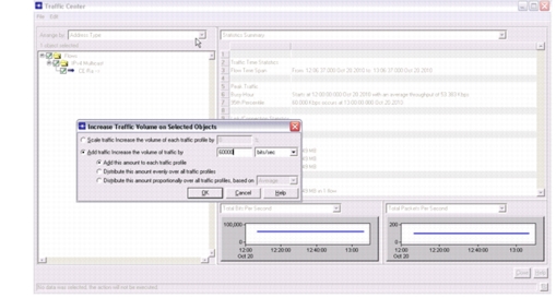
Add 60000bps to the traffic so now it becomes 120K, which will pass the threshold.
Figure 259: Increase Traffic Intensity in Traffic Center
-
-
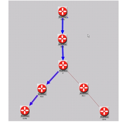
After increasing the traffic volume, run Flow Analysis again. Right-click to show routes for the flow again. Now there is no split on P. This indicates that the traffic is now riding a tree in the core that does not span to PE-C.
Figure 260: Show Routes for IP Flow
-
Examine this on the MVRF table of PE-A. Now the MDT Group is 225.2.2.1, a switch MDT tree.
Figure 261: View MVRF Table
-
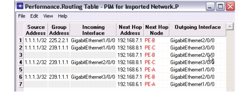
View the PIM table on the PE and P routers to verify that a switch MDT tree is created. The following shows the table on P, which has an extra entry for group 225.2.2.1, which only goes to PE-B.
Figure 262: PIM Table for PE and P Routers
-
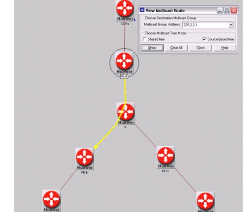
Show multicast routes on PE-A. Now 225.2.2.1 is selectable, and it only goes to PE-B.
Figure 263: Multicast Routes on PE-A
-
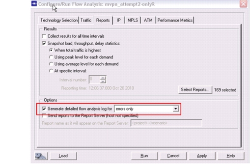
If the flows are not routable or the trees are not created, you can use the Flow Analysis Detailed Log to debug.
-
Enable the Log in the Flow Analysis dialog box, as shown below.
Figure 264: Enable Flow Analysis Detailed Log
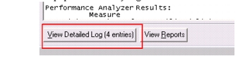
Result: After running Flow Analysis, if any entry is logged, the View Detailed Log button on the pop-out summary log will be enabled.
-
Click on the button to show the log.
Figure 265: View Detailed Log Button
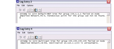
The following logs are a result of manually failing the link between PE-A and P. You can see that PE-A cannot find an RP when trying to join the share-MDT tree, and CE-Rb cannot reach the traffic source. These log entries can help debug the reasons for why the mVPN is not working as expected.
Figure 266: Detailed Flow Analysis Log Entries
-
End of Procedure 60
Problems With Existing RP Definitions
This section describes some common problems that you might encounter when configuring RP selection.
Recall that a well-defined RP has the following properties:
- defined
- reachable
The following will describe the methods you can use to troubleshoot the configuration.
Simulation Log Messages
Discrete event simulation creates log messages to report on certain events or potential problems in the simulation. You can refer to them for additional information after a simulation.
Non-Existent ACLs
Discrete event simulation reports this error using the following message.
Figure 267: Non-Existent ACLs Log Message (Discrete Event Simulation)
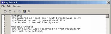
The log message states that there is a possible misconfiguration. You can use the information in the log message to correct the existing configuration.
Undefined RP Due to Missing RP Configuration
If multicast traffic traverses a node with missing RP configuration, a log message like the one shown in the following figure is generated.
Figure 268: Undefined RP Log Message (Discrete Event Simulation)
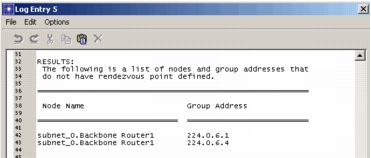
The message lists the node names and group addresses for which the RP was unknown. To correct this problem, change the configuration to include the RP definition.
No Mapping Agent for Auto-RP
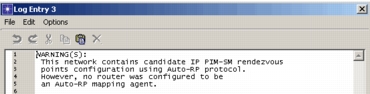
Auto-RP requires that at least one mapping agent is set. The mapping agent collects the auto-rp configuration information and sends announcements to the routers running auto-rp. If auto-rp is not configured, the following message is generated.
Figure 269: No Mapping Agent for Auto-RP Log Message (Discrete Event Simulation)
Bootstrap Not Supported
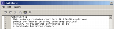
If no router is configured as a candidate bootstrap router, the following message is generated.
Figure 270: Bootstrap Not Supported Log Message (Discrete Event Simulation)
RP is Unreachable
If an RP is defined but unreachable, multicast packets are dropped and the following message is generated.
Figure 271: Unreachable RP Log Message (Discrete Event Simulation)
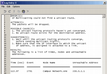
To correct this problem, you can inspect routing tables and use reachability analysis. For more information about reachability analysis, see "IP".
Problems with Traffic Not Received
Traffic not received is a common problem in multicast network models. You can find the source of the problem using discrete event simulation log messages.
Discrete Event Simulation
Log Messages
Discrete event simulation log messages are valuable sources of troubleshooting information. They are generated for the following configuration problems:
- RP configuration problems
- Host joins before multicast routing starts
- Multicast background traffic starts before hosts join
- Multicast is enabled on all routers forwarding multicast traffic
For any of the log messages mentioned above, refer to the possible causes section of the message to guidelines on how to correct the problem.
RP Configuration Problem
For problems with RP configuration, refer to the troubleshooting guidelines in Problems With Existing RP Definitions.
Application Configuration Problem
You can refer to the Application Model User Guide for more information on application configuration. Another troubleshooting technique is to use multicast demands to determine whether or not the problem resides in the application configuration.