Multicast Tree Visualization
Configuration
You can view the multicast tree in the Project Editor workspace. To do this, you need to configure the network and the multicast sources and destinations in the network. The following steps are needed to visualize a multicast tree.
- Support multicast in the network
- Create traffic sources
- Configure nodes to receive traffic from a particular group address
- Run a simulation (flow analysis or discrete event simulation)
- Visualize the multicast tree
Supporting Multicast in the Network
There are two steps to supporting multicast in a network:
- Enabling multicast traffic forwarding
- RP configuration (see Rendezvous Point (RP) Selection). This does not apply to SSM (see Source Specific Multicast).
Procedure 52: Enabling Multicast Traffic Forwarding on Physical Interfaces
-
Set the IP Multicast Parameters > Multicast Routing attribute to Enabled.
-
Select all links in the network that carry multicast packets.
-
Choose Protocols > IP > Multicast > Enable Multicasting on Interfaces across Selected Links.
Result: Interfaces are added to the tables for the following attributes: PIM Parameters, IGMP Parameters, and IP Multicast Parameters.
End of Procedure 52
The model supports multicast on the following logical interfaces:
- Subinterfaces
- VLAN interfaces
- Aggregated interfaces
- Tunnel interfaces
The following procedure describes how to enable multicast on any of the supported logical interfaces.
Procedure 53: Enabling Multicast on a Logical Interface
- Set the IP Multicast Parameters > Multicast Routing attribute to Enabled.
- For subinterfaces, add the interface into IP Multicast Parameters >
<physical_interface>><Subinterface Information> - For VLAN, Aggregated, and Tunnel interfaces, add the interface to IP Multicast Parameters attribute.
- Set the interface name.
- Set the Status to “Enabled” and the Routing Protocol to “PIM-SM”.
- Close the open dialog boxes. This automatically adds the interface to PIM Parameters > Interface Information attribute.
- (optional) To enable IGMP on the logical interface, add it into IGMP Parameters > Interface Information attribute and set its name and Status to “Enabled.”
End of Procedure 53
Creating Traffic Sources
A multicast flow can originate on router and host nodes.
Procedure 54: Creating a Multicast Traffic Flow
-
Open the demands object palette.
-
Click on the ip_mcast_traffic_flow demand.
-
Click on the origin node in the workspace.
-
Double-click on an empty space in the project workspace.
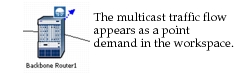
Figure 231: Multicast Traffic Flow
-
Open the flow’s Attributes dialog box.
-
Configure the Destination IP Address attribute. This is the address of the multicast group.
-
Configure the traffic profile for the multicast flow.
-
Close the Attributes dialog box.
End of Procedure 54
Configuring Nodes to Receive Traffic from a Particular Group Address
You can configure host nodes to listen to a multicast group using Procedure 56. For routers, configure the router to use static IGMP and specify the group address in the IGMP Parameters > Interface Information > Membership Groups attribute as described in Procedure 55.
Note: These procedures do not apply if you are using SSM. See Source Specific Multicast.
Procedure 55: Joining a Multicast Group (Routers)
- Select one or more routers belonging to the same multicast group.
- Choose Protocols > IP > Multicast > Set IGMP Membership Groups on Selected Routers...
- Specify the IP multicast group address.
- Click OK.
End of Procedure 55
Procedure 56: Joining a Multicast Group (Hosts)
- Select one or more nodes belonging to the same multicast group.
- Choose Protocols > IP > Multicast > Set Multicast Group on Selected Destination Nodes…
- Specify the multicast application, multicast group address, joining time, and leaving time.
- Click OK.
End of Procedure 56