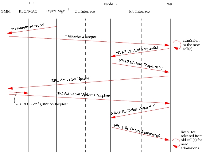
Signal Flows
GPRS Attach
For completeness, the entire GPRS Attach procedure without prior CS (Circuit Switched) traffic is shown in Figure 608. However, the model assumes (and does not explicitly model) that a PS signaling connection is already established at power-on. The GPRS Attach procedure is performed to inform the SGSN(s) of a user’s location and to set up a PS signaling connection. Once a PS signaling connection is established, the UE and SGSN(s) move from the PMM-Detached State to the PMM-Connected State.
The PS signaling connection includes the RRC signaling connection between the UE and UTRAN, and the Iu signaling connection between the UTRAN and CN. If there has been no prior CS traffic, a signaling connection is set up between the UE and UTRAN. Once an RRC signaling connection is established between the UE and UTRAN, a Service Request (signaling) message is sent to the SGSN(s) to set up the Iu connection between the UTRAN and SGSN. Once the PS signaling connection is established, the UE initiates the GPRS Attach procedure by sending a GPRS Attach Request message to the SGSN(s). The GPRS Attach Request includes the Follow On Request indication that indicates that the Iu connection should be released or kept after the GPRS Attach procedure. At this stage, the model assumes that the PS signaling connection is maintained for the duration of the simulation.
Figure 608: GPRS Attach with no Prior CS Traffic
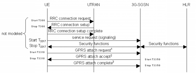
Here is how Riverbed Modeler explicitly models GPRS attach signalling:
- UE initiates the GPRS Attach procedure by sending a GPRS Attach Request (IMSI, Attach Type, Follow On Request) message to the SGSN. UE starts timer T_3310 when sending the GPRS Attach Request message. The Attach Type is set to GPRS Attach only and the Follow On Request indication is set to keep the Iu connection.
- Upon receipt of the GPRS Attach Request message, the SGSN sends the UE an Attach Accept (P‑TMSI) message and starts timer T_3350. In the current model, P‑TMSI is always included in the Attach Accept message.
- Upon receipt of the GPRS Attach Accept message, the UE stops timer T_3310 and responds to the SGSN with an GRPS Attach Complete message.
On receipt of the GPRS Attach Complete message, the SGSN stops timer T_3350, which completes the GPRS Attach procedure.
PDP Context Activation and RAB Assignment (MS-Connected State)
The PDP Context Activation procedure is required when the PDP context for the requested class of service is inactive. Figure 609 and Figure 610 show the PDP Context Activation procedures initiated by the UE and CN, respectively. If the UE is in PMM-Idle State, the UE first performs a Service Request Procedure to set up a PS signalling connection and enter the PMM-Connected State before initiating the PDP Context Activation procedure. Once the GPRS Attach procedure is completed, the UE remains in the PMM-Connected State for the rest of the simulation.
Figure 609: PDP Context Activation Procedure Initiated by the UE (Connected State)
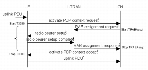
- When the UE receives Protocol Data Units (PDUs) from higher layers, it initiates the PDP Context Activation Procedure if the PDUs belong to a quality of service that does not yet have an activated PDP context. The UE initiates the PDP Context Activation procedure by sending an Activate PDP Context Request (PDP Type, QoS Requested) message to SGSN. The UE starts T_3380 when sending an Activate PDP Context Request message. In the model, only one PDP Context per QoS is set up and the PDP Type corresponds to the QoS requested.
- On receipt of the Activate PDP Context Request, the SGSN sends a RAB Assignment Request message to the RNC (Radio Network Controller) to establish a RAB (Radio Access Bearer). The SGSN starts the T_RABAssgt timer when sending a RAB Assignment Request message.
- On receipt of a RAB Assignment Request message, the RNC performs admission control. If sufficient uplink and downlink capacity is available, the RNC establishes the appropriate radio bearer by sending a Radio Bearer Setup message to the UE.
- On receipt of a Radio Bearer Setup message, the UE sets up the appropriate radio bearer as specified by the RNC. The UE then sends a Radio Bearer Complete message to the RNC.
- On receipt of the Radio Bearer Complete message, the RNC sends a RAB Assignment Response message to the SGSN.
- On receipt of a successful RAB Assignment Response, the SGSN normally sends a Create PDP Context Request (PDP Type, QoS Negotiated) to the GGSN. However, since the SGSN and GGSN are modeled as a single node, this procedure is not modeled. However, a new entry in the PDP context table is created as would be done at the GGSN. When completed, the SGSN sends an Activate PDP Context Accept message to the UE. If the RAB Assignment procedure is unsuccessful because the requested QoS profile cannot be provided, the UE tries to activate the PDP Context at a later time. Because the model always negotiates a QoS that matches the QoS Requested, the SGSN model does not send a new RAB Assignment Request message with a different QoS profile. On receipt of a RAB Assignment Response, the SGSN stops the T_RABAssgt timer.
- The UE stops the T_3380 timer on receipt of an Activate PDP Context Accept message, completing the PDP Context Activation procedure. The UE is now ready to send any PDUs with a QoS matching the PDP context it has activated.
Figure 610: PDP Context Activation Procedure Initiated by the Network (Connected State)
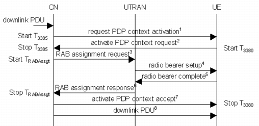
- Since the SGSN and GGSN are modeled as a single node, the PDU Notification procedure is not modeled. Instead, the combined SGSN/GGSN node initiates the Network-Requested PDP Context Activation procedure by sending a Request PDP Context Activation message to the UE. It starts T_3385 when sending the Request PDP Context Activation message. The combined SGSN/GGSN stores any subsequent PDUs for the same quality of service until the PDP context has been activated.
- On receipt of the Request PDP Context Activation message, the UE initiates the PDP Context Activation procedure, as described above. The CN stops T_3385 on receipt of the Activate PDP Context Request message from the UE.
RAB Assignment with Prior PDP Activation (MS-Connected State)
If an active PDP context for the requested QoS already exists, the PDP Context Activation procedure is not required. However, if there is no radio access bearer for the active PDP context, the RAB Assignment procedure must be initiated. Figure 28 and 29 show the RAB Assignment procedure initiated by the UE and CN, respectively when a PDP context for the requested QoS is already active. If the UE is in the PMM-Idle State, the UE first needs to perform a Service Request Procedure to set up a PS signalling connection and enter the PMM-Connected State before initiating the RAB Assignment procedure. Once the GPRS Attach procedure is completed, the UE remains in the PMM-Connected State for the rest of the simulation. Thus, the diagrams assume that the UE is already in PMM-Connected State.
Figure 611: RAB Assignment Procedure Initiated by the UE (Connected State)
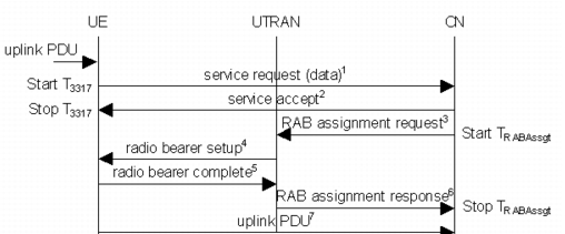
- On receipt of PDUs from higher layers, the UE initiates the RAB Assignment procedure if these PDUs belong to a quality of service for which a PDP context has already been activated but for which no radio bearer has been established. The UE initiates the RAB Assignment procedure by sending a Service Request (P‑TMSI, Service Type) message to the SGSN. Service Type specifies the requested service. Service Type can be set to Data or Signaling. In this case, the Service Type is set to Data. The UE starts T_3317 when sending the Service Request message.
- On receipt of the Service Request, the SGSN sends a Service Accept message to UE. The UE stops its timer T_3317 on receipt of the Service Accept message.
- On receipt of the Service Request (Data), the SGSN initiates the RAB Assignment procedure by sending a RAB Assignment Request to the RNC. The RAB Assignment procedure was previously described.
Figure 612: RAB Assignment Procedure Initiated by the Network (Connected State)
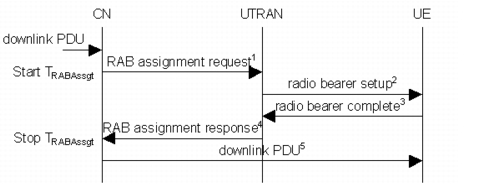
- On receipt of PDUs, the CN determines if the Network-Requested PDP Context Activation procedure has to be initiated. Since a PDP Context is already active for the quality of service requested, the combined CN node initiates the RAB Assignment procedure previously described.
PDP Context Modification with RAB Modification
The signaling flow for PDP context modification with RAB modification are shown in the following diagram:
Figure 613: Signal Flows for PDP Context Modification with RAB Modification
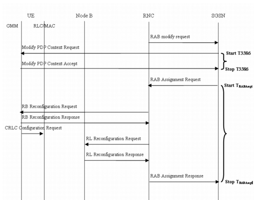
- The RNC modifies an existing RAB by sending a RAB Modification request to the SGSN.
- On receipt of the RAB Modification request, the SGSN initiates a PDP Modification procedure by sending a PDP Context Modification request to the UE. The SGSN starts its timer T3386.
- On receipt of the PDP context modification request, the UE responds to the SGSN with a PDP Context Modification Accept message.
- On receipt of the PDP Context Modification Accept message from the UE, the SGSN modifies the appropriate RAB by sending a RAB Assignment request (Modification) to the RNC. The SGSN stops its timer T3386 and starts the timer TRABAssgt.
- On receipt of the RAB Assignment request (Modification), the RNC modifies the appropriate radio bearer by sending a Radio Bearer Reconfiguration message to the UE.
- On receipt of the Radio Bearer Reconfiguration message, the UE reconfigures the appropriate radio bearer as specified by the RNC. The UE then sends a Radio Bearer Complete (Reconfiguration) message to the RNC.
- On receipt of the Radio Bearer Complete (Reconfiguration) message, the RNC modifies the appropriate radio link by sending a Radio Link Reconfiguration message to the node B.
- On receipt of the Radio Link Reconfiguration message, the node B reconfigures the appropriate radio link as specified by the RNC. The node B then responds to the RNC with a Radio Link Reconfiguration Response message.
- On receipt of the Radio Link Reconfiguration Response, the RNC sends RAB Assignment Response (Modification) message to the SGSN.
- On receipt of the RAB Assignment Response (Modification) message, the RNC modifies the appropriate PDP context. The SGSN stops its timer TRABAssgt.
RNC to Node-B Signal Flow
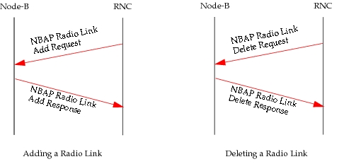
The signalling messages for adding and deleting a radio link are shown in the following diagram:
Figure 614: Signal Flows for Adding and Deleting a Radio Link
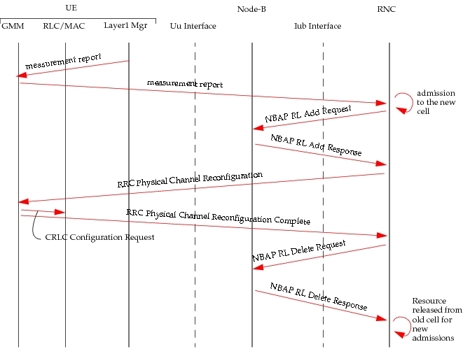
Signal Flows for Hard Handover
The following figure shows the signalling messages used in hard handover.
Figure 615: Signaling Messages for Hard Handover
Signal Flows for Soft Handover
The following figure shows the signalling messages used in soft handover.
Figure 616: Signaling Messages for Soft Handover: In Case of Event 1C (Cell Replacement)