Node-B Architecture
The Node-B manages the network’s air interface for UEs in the same sector as the Node-B. There are both ATM and IP-enabled Node-Bs. The model suite includes a single-sector Node-B, a three-sector Node-B, and a six-sector Node-B. An RNC connects to one or more Node-Bs to communicate with the UEs of the network and to manage multiple calls.
Node-B Node Model Architecture
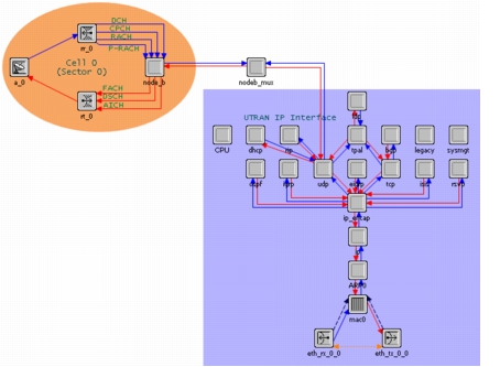
The Node-B node models include one node_b processor module for each sector it manages. The node_b processor module is connected to an ATM or IP protocol stack, a transmitter module, and a receiver module. Each packet stream between the node_b module and the transmitter represents a downlink channel and each stream between the node_b module and the receiver represents an uplink channel. In the downlink direction, packets are forwarded to the transmitter on the FACH or DSCH streams, or on the dedicated channel via op_pk_deliver(). In the uplink direction, all packets travel over the RACH, CPCH (not modeled in the current release), or DCH streams. All DCH packets converge at the DCH input stream, regardless of their channel or spreading code.
Figure 590: Node-B Node Model
Node-B Process Model Architecture
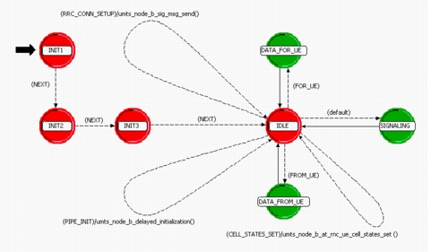
When the simulation starts, Node-Bs initialize the data structures used in the pipeline stages, sets radio transmitter and receiver attributes for all UEs and Node-Bs in the UMTS network (only the first Node-B to start performs this task), and initializes ATM-VC or IP connections to the RNC for each QoS class and signalling data channel.
Besides relaying packets between UEs and the RNC, the Node-B also assists the RNC with radio resource management through NBAP (Node-B Application Protocol) signalling messages. When the RNC receives a request to add a new radio link, it informs the Node-B of the addition of this link for the call. The Node-B then responds to the request with assigned spreading code for the radio link. A similar communication happens between Node-B and RNC for radio link deletions. RNC informs Node-B about the deletion request, and Node-B frees the spreading code assigned for that link, before responding to the RNC.
When the RNC receives a request to modify a radio link, it informs Node-B of the modification of this link. Once complete, Node-B responds to the RNC.
Figure 591: umts_node_b Process Model
Node-B Repeaters
A repeater can be used to extend the coverage area of a Node-B cell, improve signal strength (especially in downlink), and get around physical obstacles. For example, UE travels from one cell to another through an area of coverage loss. With a repeater added to the first cell, UE can travel from one cell to another without losing connectivity.
Repeaters transmit received Node-B transmissions in the downlink direction, and UE transmissions in the uplink direction. Repeater transmissions add to interference in both directions, which must be considered in interference computations.
- Uplink: Interfere with simultaneous receptions at donor Node-B (unless fiber link to donor Node-B is used.) A given Node-B cell does not hear packets or interference from any repeaters to which it is not associated.
- Downlink: Interfere with simultaneous receptions at all UEs. A repeater only repeats packets with its donor Node-B cell.
A repeater forwards packets regardless of number of bit errors. Bit errors in packets received at the repeater are still present in the packet when it is received at the final destination (or next hop.)
Repeaters amplify received packets in accordance with repeater gain settings (may be different in uplink/downlink directions.) Each Node-B cell may have multiple associated repeaters.