UMTS Timing
The following timing delays are modeled:
- Encoder delay
- Processing delay
- Buffering delay
- Propagation delay (configurable)
- IP delay (configurable)
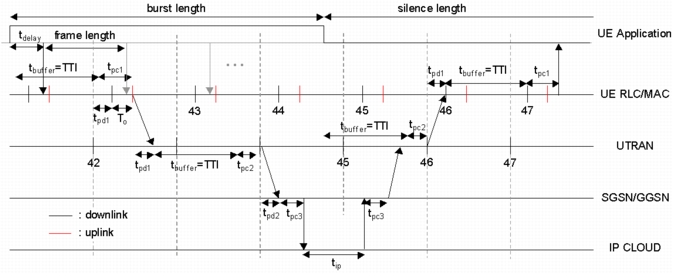
Figure 603 shows how these delays are implemented in the model. The encoder delay represents all delay incurred by the encoder in the first and subsequent frames of a burst (T_delay). At the RLC/MAC layer, data is first buffered for one transmission time interval (TTI), which can last from one to eight times the length of one radio frame (10-80 ms). Data is then processed (coded, interleaved,…).
The processing delay is the time required by the transmitter and receiver to process the packet. The processing delays at the UE, RNC, and SGSN/GGSN are labeled t_pc1, t_pc2, and t_pc3, respectively.
At the UE and UTRAN, packets can be sent on a frame boundary if the channel is not already busy. For example, if a packet at the UE is received from higher layers at least t_pc1 before the frame boundary, the packet can be sent at the next frame boundary, if it is available. Otherwise, it waits an additional transmission time interval.
At the receiver, the buffering time (T_buffer) represents the time needed by the receiver to buffer all of the radio frames required to decode the signal. The propagation delay is based on the distance and on the type of channel link: t_pd1 represents the propagation delay between the UE and UTRAN and t_pd2 represents the propagation delay between the UTRAN and SGSN/GGSN. The IP delay (t_ip) is the delay through the IP cloud.
Figure 603: Delay in RAN and CN Network