UE Architecture
Three types of UEs are supported in the UMTS model: simple mobile stations (umts_station), advanced workstations (umts_wkstn), and advanced servers (umts_server). You can model your UE nodes as either fixed (fix) or mobile (mob). Use the mobile node when the UE you are modeling moves during the simulation. You can reduce simulation run times by using the fixed nodes to model UEs that do not move during simulation.
UE Node Model Architecture
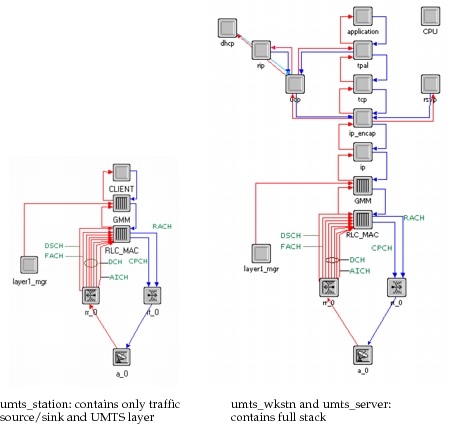
The UMTS station model shown in Figure 582 includes an application layer that feeds directly into the GMM layer. It also includes the RLC/MAC layer, a radio transmitter and receiver, and one antenna.
The advanced workstation and server (Figure 582) include the full TCP(UDP)/IP protocol stack between the application layer and GMM layer.
The GMM layer contains functions from the GMM, GSM, and RRC layers. It has mobility management functions (such as GPRS attach), session management functions (such as PDP context activation), and radio resource control functions (such establishment and release of radio bearers). The RLC/MAC layer contains the RLC and MAC layers. It includes priority handling of data flows, the three types of RLC modes, and segmentation and reassembly of higher-layer packets.
The links between the radio transmitter and the RLC/MAC layer and between the radio receiver and the RLC/MAC layer represent transport channels. On the uplink, there can be one random access channel (RACH), one common packet channel (CPCH), and one dedicated channel (DCH) where signaling and data traffic converges. Each transport channel in the dedicated channel has a unique spread code that distinguishes it from other transport channels. On the downlink, there can be one forward access channel (FACH), one downlink shared channel (DSCH), one acquisition indicator channel (AICH), and one dedicated signaling channel per user, and up to four data channels. The number of signaling and data channels on the downlink is equal to the number of signaling and data channels on the uplink; the exception to this is the DSCH, which has one extra channel. Each channel is assigned a different spread code and traffic on all channels can be sent simultaneously.
Figure 582: Simple and Full-Protocol Stack UE Node Models
The RLC is assigned a logical channel according to an application’s DiffServ characteristics. MAC uses a queuing scheme in combination with logical channel weights/priorities to multiplex and schedule data from logical to transport channels. Logical channels transport control/data between L2/RLC and L2/MAC. Transport channels transport data between L2/MAC and L1. Users can map higher layer data to logical channels using either ToS or DiffServ priority handling, and multiplex logical channels to transport channels using a queuing scheme. This capability allows custom classes to be defined (i.e., prioritizing certain cell phone traffic sources over others), and increases the granularity of application performance metrics to observe scheduling behavior.
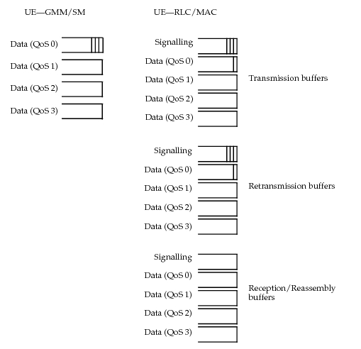
The queue structure at the GMM and RLC/MAC layers is shown in Figure 583. The GMM layer has four queues, one for each QoS class the UE can support. When a data packet from the application layer arrives at the GMM layer, it is forwarded to the RLC/MAC layer if a channel has already received a RAB setup message for the RAB of the packet’s QoS class. Otherwise, the packet is enqueued at the GMM layer in the queue corresponding to its QoS profile. The RLC/MAC layer uses queues to transmit packets coming from higher layers, to retransmit packets in RLC acknowledged mode, and to receive packets from lower layers and reassemble them to build the PDUs from these packets. Each category requires one queue for signaling and four queues for each QoS supported.
Figure 583: Queue Structure for GMM and RLC/MAC Layer at the UE Node
UE Process Model Architecture
The process models for the application layer of the UE station node model are shown in Figure 584 (umts_client_mgr) and Figure 585 (umts_client_child). When the umts_client_mgr process model is invoked—either at the start of a new session for a particular QoS class or when triggered by another user (passive session)—it spawns the umts_client_child process. The child process is killed when the session ends. There are as many simultaneous child processes opened, as there are simultaneous sessions active at the UE.
When peer-to-peer communication is enabled at the caller side, transfer is done in both directions. In this case, the application layer at the originating UE, referred to as the mobile origination, first starts an active session. To set up a channel, the mobile origination (MO) sends a SETUP message to the mobile termination (MT). Once a channel is set up, the mobile termination sends a CONNECT message to the MO and starts sending data to MO. When the MO receives the CONNECT, it also starts sending data packets to MT. When peer-to-peer communication is not enabled, transfer occurs only in one direction. When a channel is setup on the mobile origination side, packets are sent directly to the mobile termination. No initial message sent to set up the channel on both sides as in peer-to-peer communication. Therefore, data packets are queued at the termination side until a channel is set up with the mobile termination.
Figure 584: umts_client_mgr—Application Manager Process for the UE Station Node
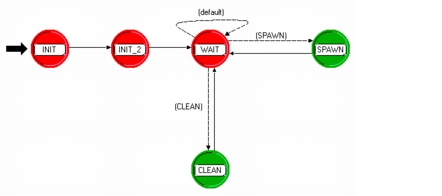
Figure 585: umts_client_child—Application Child Process for the UE Station Node
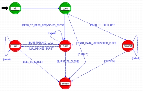
Figure 586 shows the process model for the UE’s GMM layer. Upon completion of GPRS attach, the UE waits in the CONNECTED state. As soon as the GMM layer receives packets from higher layers for a new QoS class, it sends a request to the SGSN to activate the PDP context. Once the PDP context is activated and a channel is set up, the UE can send packets to their destination. Modification of active PDP context is also supported. If the GMM layer receives packets from higher layers in the CONNECTED state when the PDP context is already activated but no radio bearer is set up, the UE sends a service request to SGSN. A channel is then set up and the UE can start sending packets to its destination. The radio bearer release and reconfiguration is also modeled in this process model. If the PS connection is released, the user moves to the IDLE state. The IDLE state and the RAU (Routing Area Update) state are not modeled in the current release.
Figure 586: umts_gmm—GMM Layer Process Model on the UE
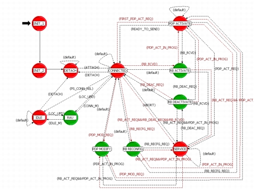
Figure 587 shows the process model for the RLC/MAC layer, umts_rlc_mac. This process handles segmentation and reassembly of higher layers PDUs into and from smaller RLC PUs. It also handles transparent, unacknowledged, and acknowledged RLC modes. In unacknowledged and acknowledged RLC modes, umts_rlc_mac adds RLC and MAC headers to each PU. Packets coming from higher layers are buffered in different queues according to the channel a packet will be sent on. Packets are taken out of the buffer in each frame. If the frame boundary corresponds to the beginning of a transmission time interval (TTI) for that channel and the packet was received early enough to allow for processing time, the packet is segmented, RLC and MAC headers are added when appropriate, and the resulting packet is sent to the transmitter on the correct channel. For packets received from lower layers, packets are simply delayed by the processing time, and then forwarded to higher layers.
Figure 587: umts_rlc_mac Process for the UE’s RLC/MAC Layer
The RLC/MAC layer models all three RLC retransmission modes. For RLC Transparent Mode (TrM), Protocol Data Units (PDUs) from higher layers are segmented into smaller RLC Payload Units (PUs) and transparently transmitted to lower layers, and vice versa for reassembling PDUs from lower layers. There is no need to add RLC/MAC headers to or remove RLC/MAC headers from these packets. In RLC Unacknowledged Mode (UM), PDUs are segmented and reassembled, and RLC/MAC headers are added to each segment. Each segment is tagged with a sequence number but missing segments are not retransmitted.
For RLC Acknowledged Mode (AM), PDUs from higher layers are segmented into smaller RLC PUs, and RLC and MAC headers are added to each segment. Similarly, the RLC and MAC headers are removed from segments from lower layers, which are then reassembled into PDUs. As in the unacknowledged mode, each segment is tagged with a sequence number.
When the RLC/MAC layer of the receiving UE or RNC detects a missing segment, it sends a STATUS REPORT to the transmitting RNC or UE asking for the missing segment. On receipt of the STATUS REPORT from the receiver, the transmitting UE or RNC retransmits the missing segment. Retransmitted segments have higher priority than segments being transmitted for the first time. A segment can be retransmitted up to MAX_DAT times before it is discarded.
When segment is discarded after the maximum number of failed retransmissions attempts, the channel is locked and is reset. The RLC AM reset procedure can be triggered at the UE or at the RNC and is handled differently in each case.
- For RLC AM reset cases at the UE—the affected channel is blocked and all data traffic intended for that channel is discarded. Other transport channels serving different QoS classes remain active unless they also encounter a reset situation.
- For RLC AM reset cases at the RNC—the affected logical/transport channel (identified by IMSI and QoS) is blocked and the radio bearer (RB) corresponding to that channel is released. The model also considers the possibility that the RB release procedure with the UE can also fail if the UE loses communication through the signalling channel. In these cases, the RB is released after a certain number of trials.
In both reset cases, the model does not support recovery from a reset situation—a channel blocked during reset will remain blocked for the remainder of the simulation.
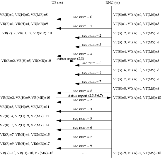
The transmitter and receiver also have a Transmission Window Size and a Receiver Window Size. The Maximum Send state variable (VT(MS)) is equal to the Transmission Window Size plus the sequence number of the next in-sequence PU expected to be acknowledged (VT(A)) plus the sequence number of the next PU to be transmitted for the first time (VT(S)). The Maximum acceptable Receive state variable (VR(MR)) is equal to the Receiver Window Size plus the sequence number of the next in-sequence PU expected to be received. The number of segments sent to the receiver, but awaiting acknowledgement should not exceed the Transmission Window Size. Similarly, the receiver will not accept segments exceeding the Receiver Window Size from the transmitter, and discards excess segments.
The RLC Acknowledged Mode also uses several timers. STATUS REPORT messages are sent every Timer_Status_Periodic and each time a missing segment is detected at the receiver if the Missing_PU_indicator is set to TRUE. Every time a STATUS REPORT is sent, another timer Timer_Status_Prohibit is started. The receiver cannot send a STATUS REPORT while the Timer_Status_Prohibit is active. On expiry of Timer_Status_Prohibit, a STATUS REPORT is sent if Timer_Status_Periodic expired or missing segments were detected while Timer_Status_Prohibit was active.
Every segment sent by the transmitter for the first time is copied and saved in a retransmission buffer. When the transmitter receives an acknowledgement from the receiver, it removes the acknowledged segments from the retransmission buffer. If a segment stays in the retransmission buffer longer than Timer_Discard, it is discarded. This prevents build-up of buffer length at the transmitter when there are frequent retransmissions.
Figure 588 shows the retransmission procedure in RLC acknowledged mode between the RNC (transmitter) and the UE (receiver) including the variables required to keep track of missing packets. In Figure 588, the Transmission Window Size and the Receiver Window Size are 8 PUs. When VT(S) and VT(MS) equal 8, the transmitter cannot send additional PUs until it receives an acknowledgement from the receiver. When the transmitter receives a STATUS REPORT, it retransmits the missing PUs and updates its VT(A) and VT(MS) variables based on the sequence number acknowledged in the STATUS REPORT.
Figure 588: RLC AM Retransmission
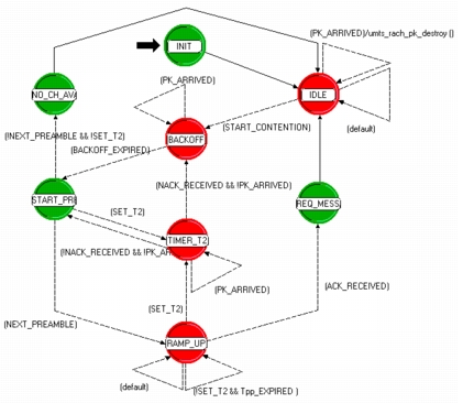
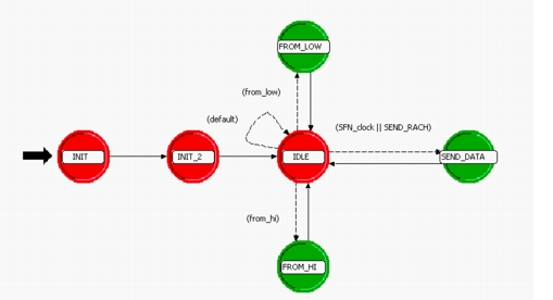
When the UE is in the CELL_FACH state, the RACH (random access channel) is used to transmit data in the uplink direction. When packets are buffered at the RLC/MAC layer, the RLC/MAC spawns the umts_rach process, which models the random access channel. The umts_rach process model, shown in Figure 589, follows the slotted aloha contention algorithm. The process uses the preamble ramp-up procedure to begin sending preambles. Once it receives an acknowledge from the node B, umts_rach notifies the RLC/MAC so that data messages can be sent.
Figure 589: umts_rach Process Model on the UE