RNC Architecture
The RNC manages the resources of the air interface of all the UEs on Node-Bs serviced by the RNC. The RNC does the following management tasks:
- Coordinates the admission control process of establishing and tearing down RABs for UEs requesting service over various QoS classes.
- Finds needed resources for new requests by reorganizing the resource allocations and negotiating/renegotiating QoS parameters on new or already established RABs.
- Manages the handovers of UEs between its Node-B due to UE’s movements between the cells.
- Buffers packets destined for UEs per QoS class.
- Communicates with the SGSN(s) allowing the SGSN(s) to send and receive data to and from the UEs it services.
- Performs related tasks as the peer of the RLC and MAC layers of the served UEs.
- Monitors the activity on the established radio bearers to tear them down in case of inactivity.
RNC Node Model
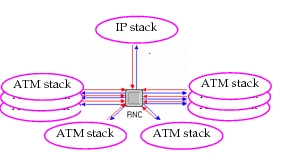
The RNC Node model consists of the “RNC Manager” and three child processes that perform the functionality of the RNC. The RNC Manager has nine ATM or IP stacks attached to it, one of which connects to the SGSN(s) servicing the RNC. The other eight will connect to Node-B ATM or IP stacks. The RNC process models can determine which type of node exists at the other end of any given connection, so the RNC can connect any of these stacks to either a Node-B or SGSN so long as no more than one RNC connects to it and at least one Node-B connects to it. The total number of supported node-Bs can be increased by adding more ATM or IP stacks to the node structure.
Figure 592: RNC Node Model
RNC Process Model
The model suite includes four process models: umts_rnc (the RNC Manager), umts_rnc_rlc_mac, umts_rnc_ranap_nbap, and umts_rnc_rrc.
Figure 593: RNC Model Root and Child Processes
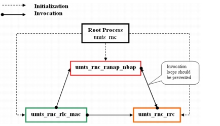
Specifically:
- The umts_rnc_rlc_mac process implements Radio Link Control (RLC)/ Medium Access Control (MAC) functions.
- The umts_rnc_ranap_nbap process implements handle signaling with Node B Application Part (NBAP), and handle serving gateway support node (SGSN) signaling with Radio Access Network Application Part (RANAP), and
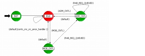
- The umts_rnc_rrc process implements initialization and user equipment (UE) signaling with Radio Resource Control (RRC) procedures, including admission control, handover, and mobility related procedures.
The umts_rnc_rlc_mac process receives stream/remote interrupts to the RNC module. Once created, it is responsible for invoking other child processes accordingly.
The umts_rnc_rlc_mac process maintains arrays of queues that each serve a specific purpose: transmission, reception, retransmission, segmentation, and reassembly. Each position in the array represents the set of buffers (or queues) that are assigned to a specific channel. Some of these channels are assigned and released dynamically during the simulation while others are assigned for the duration of the simulation. The RNC designates an equal number of slots in this array for each Node-B it services. A queue array created for a Node-B has the structure depicted in Figure 594.
Figure 594: Queue Allocation Structure at the RNC
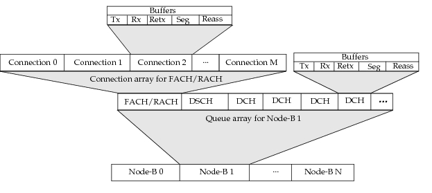
The active connections for the FACH/RACH and DSCH channels are stored in two distinct arrays.
When the simulation starts, the RNC dedicates slot 0 to the FACH/RACH and slot 1 to the DSCH, both of which point to the appropriate connection arrays. After startup of the UEs via the GPRS Attach procedure, the RNC establishes a signalling DCH for each UE. As the RNC creates DCHs, it dedicates slots in the array in the section it reserved for the Node-B serving the UE that the RNC establishes the channel for. As the simulation progresses and as the UEs send service request messages to get DCH RABs, the RNC creates channels for the new RABs that do not run over common channels. The RNC also designates unused slots in its queue arrays to service the UE’s newly established RABs. If the newly created RAB runs over common or shared channels, a new connection slot is assigned.
Figure 595: Sample Queue Allocation for an RNC
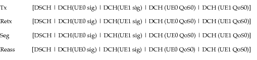
Figure 596: umts_rnc and umts_rnc_rlc_mac Process Models
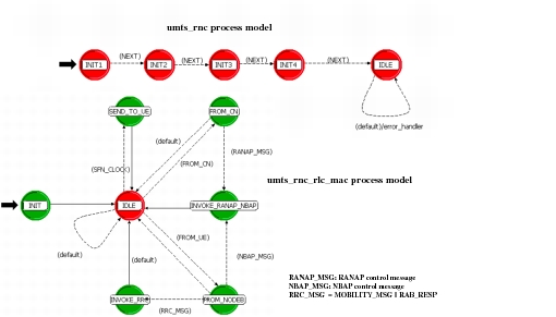
Figure 597: umts_rnc_ranap_nbap Process Model
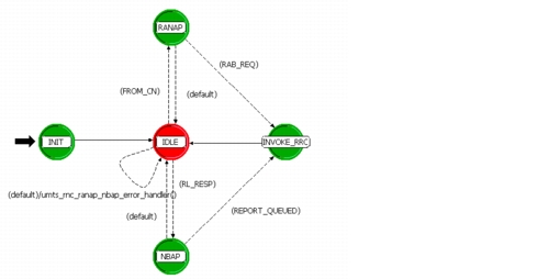
Figure 598: umts_rnc_rrc Process Model