Configuring IP Interfaces
The model suite supports the following types of IP interfaces:
- Physical interfaces
- Subinterfaces
- Loopback Interfaces
- Tunnel Interfaces
By default, router models have one loopback interface and no subinterfaces or tunnel interfaces pre-configured. You can add additional loopback, tunnel, or subinterfaces by configuring attributes, as described in the following sections.
Note: The number of physical interfaces is defined in the router model and cannot be changed. If you need a different number of physical interfaces, select another router model from the Object Palette or use the Device Creator to create a new router model that has the number of interfaces you need.
Loopback Interfaces
By default, all router models include one pre-configured loopback interface. You can add additional loopback interfaces, if needed.
Procedure 34: Configuring Loopback Interfaces on a Router
- Open the Attributes dialog box for the router.
- Expand the IP > IP Routing Parameters > Loopback Interfaces attribute.
- Specify an address for the interface in the Address and Subnet Mask attributes.
- Specify the routing protocol(s) running on the interface.
- If there are any secondary addresses associated with this interface, specify them in the Secondary Address Information attribute.
- Add additional loopback interfaces to the router by increasing the Rows attribute and repeating the previous steps for the additional interfaces.
End of Procedure 34
Tunnel Interfaces
Unlike physical interfaces, router models do not have pre-defined tunnel interfaces. Before you can configure these types of interfaces, you must first add them to the router model.
Procedure 35: Configuring Tunnel Interfaces on a Router
-
Open the Attributes dialog box for the router.
-
Expand the IP > IP Routing Parameters > Tunnel Interfaces attribute.
-
Specify the number of tunnel interfaces in the Rows attribute.
-
Configure the attributes for each tunnel interface.
Note: For multiple interfaces, you can reduce the total configuration required by creating only one interface, configuring it, then duplicating the configured interface.
End of Procedure 35
Subinterfaces
A subinterface is a mechanism that allows a single physical interface to support multiple logical interfaces. By using subinterfaces, several logical interfaces can be associated with a single hardware interface. Subinterfaces are particularly useful for routing various protocols over partially-meshed frame relay networks. In Riverbed Modeler, subinterfaces are implemented in the following protocols: ATM, Frame Relay, Serial, and VLAN.
Subinterfaces provide a flexible solution to the issues caused by split-horizon, wherein a routing update received on an interface cannot be retransmitted out onto the same interface. By dividing the partially-meshed network into a number of PVCs, each with its own subinterface, the split-horizon limitation is overcome.
As an example of the use of subinterfaces, consider the following diagram:
Figure 175: Routing Without Subinterfaces
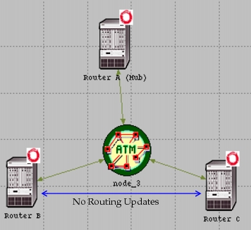
Router A can exchange routing information with Routers B and C, but B and C cannot exchange routing information with each other, as split-horizon does not allow Router A to send routing updates received from Router B to Router C, and vice versa. The solution is to create a pair of point-to-point Permanent Virtual Connections (PVCs), attached to separate subinterfaces on Router A. Now routing updates received from B or C can be forwarded to the other on a separate logical interface without violating split horizon:
Figure 176: Routing with Subinterfaces
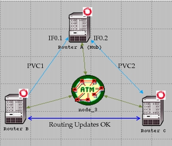
In the example above, IF0.1 and IF0.2 are the subinterfaces defined for Router A. They are attached to PVC1 and PVC 2, respectively, thereby creating separate logical connections. Thus when Router A receives routing information from Router B through subinterface IF0.1, it can forward it to Router C through subinterface IF0.2 without violating split horizon.
To use subinterfaces in a network model:
-
Define the PVCs that are to use the subinterfaces.
- To define an ATM PVC, go to "ATM" and follow the steps in "Configuring ATM" on page 15.
- To define a Frame Relay PVC, go to "Frame Relay" and follow the steps in "Configuring PVCs" on page 5.
-
Create the subinterfaces and attach a PVC to each, as described in the procedure below.
Procedure 36: Adding a Subinterface and Attaching it to a PVC
- Select a router and right-click to edit attributes.
- Expand IP > IP Routing Parameters.
- Double-click on the value field of Interface Information to open the Interface Information table.
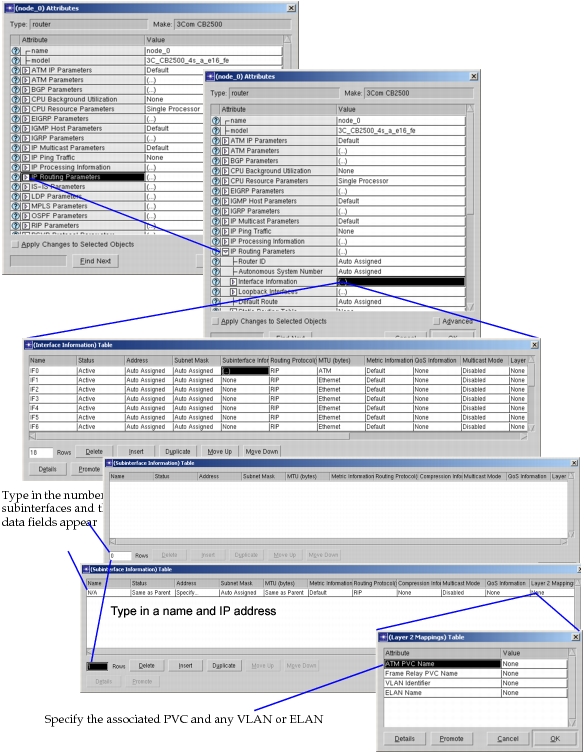
- Under the Subinterface Information column, click on the interface for which you want to define one or more subinterfaces, and select Edit.
- Click in the Rows field and select the number of subinterfaces you want to define. One row of data fields appears for each subinterface.
- Type a name for each subinterface. Subinterfaces are typically given their parent's name followed by a dot-suffix, such as IF0.1, IF0.2, and so on.
- Type an IP address for each subinterface. You cannot use auto-addressing for subinterfaces.
- Specify level 2 mapping by clicking on the Level 2 Mapping attribute field and selecting Edit. Here you can specify the associated PVC name (either ATM or Frame Relay) and the VLAN or ELAN identifier, if applicable. This needs to be done on only one of the end points of the PVC, but it is better to do it at both ends, as it will help detect configuration errors more easily.
- Specify any other attributes, as necessary.
End of Procedure 36
Figure 177: Adding a Subinterface
Auto-Assign IP Addresses Utility
Using the Auto-Assign IP Addresses utility, you can specify a starting subnet address for both IPv4/IPv6 addresses.
Specifying Starting Subnets for IPv4 and IPv6 Auto-Addressing
You can configure a starting IPv4 or IPv6 subnet address by clicking the "Start with network address," as shown in the following figure.
Note: This utility does not create new interfaces (physical or logical) and only assigns IP addresses on those interfaces already present in the network model. Interfaces with addresses set to "Auto Assigned" are given new addresses. Shutdown interfaces and those with "No IP Address" are ignored.
Figure 178: Using the Auto-Assign IP Addresses Utility
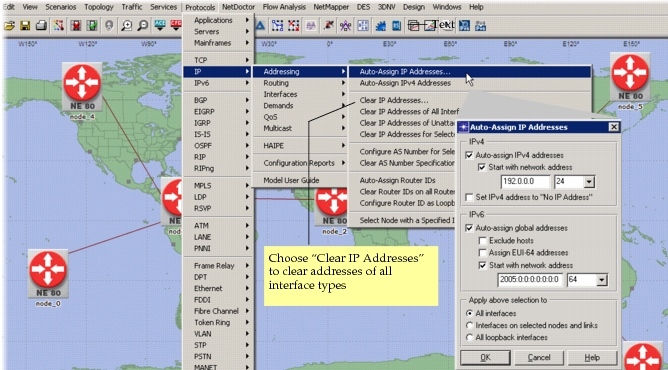
Key Concept— The Auto-Assign Utility assigns addresses to physical, loopback and aggregate interfaces and ensures that addresses assigned are not overlapping with existing addresses on any of the physical or logical interfaces.
When you specify a starting network address and a prefix length, the utility attempts to address the subnets starting from that network and increments for each subnet—adjusting the prefix length if needed. For example, if a specified prefix length is 30 and if there are 10 hosts in a given subnet, it would adjust that to use 28.
Loopback interfaces of all devices can be addressed with a separate network address—for example, 200.x.x.x, while using the "All loopback interfaces" option. A prefix length of 32 is honored while assigning addresses to loopback interfaces and interfaces on hosts.