Configuring Frame Relay
The following components are provided by the standard model library to support you in implementing Frame Relay-based network models:
- FR-enabled clients and servers for direct access to the FR network
- FR-capable routers with at least one interface supporting FR
- FR switches for constructing the core of the FR network
- FR clouds, providing an abstract way to specify the FR network core
- A special utility object called "FR-PVC-Config", facilitating PVC configuration
Configuring PVCs
PVC configuration is the most important aspect of Frame Relay network specification. The standard model library provides you with two options for setting up your network's PVCs:
- Specify PVCs via demand objects
- Import PVCs from a text file
The advantage of the first approach is that it is a simple approach that lets you set up PVCs quickly and define the Layer 2 mapping on each endpoint. The disadvantage is that if you have many PVCs, it could take an inordinate amount of time to set up all of the endpoints.
Note: To add a Frame Relay demand object to your network model, open the Frame Relay object palette and drag the "fr_pvc" object to the workspace.
The second approach is generally favored for larger network models, since it centralizes configuration information. It also provides a mechanism for importing PVC data from an external file. Such a file is easily prepared and managed using a spreadsheet application or a general text editor. To use this "import" feature, deploy the special object "FR-PVC_Config" and edit its "PVC Configuration File" attribute.
Regardless of the method you choose to specify PVCs, you are providing the Frame Relay model with identical information. In particular, you must specify the PVC name, the source endpoint of the demand, the destination endpoint of the demand, and the contract parameters.
Note: If you do not specify a name for the PVC, the default name is <source_endpoint_name>-<destination_endpoint_name>.
Endpoint nodes are specified by the value of their "name" attribute, which must be unique in the subnet. In other words, you can use the same name for two PVC endpoint nodes as long as they are in separate subnets of your network model. Within a subnet, each PVC endpoint must have a unique name. Each PVC is identified by its name, which must be unique within the entire network.
The traffic contract parameters use the standard terminology employed by FR service providers. Since PVCs are bidirectional you can specify a set of parameters for each direction, termed "incoming" and "outgoing". These terms are defined with respect to the source and destination node attributes in the "PVC Endpoints" compound attribute. The value "Same" can be assigned to the "incoming" parameters to specify that they should be identical to the "outgoing" parameters.
For each direction, you are asked to specify the committed information rate or CIR. This essentially refers to the bandwidth of your connection, though FR allows for bursts to exceed this for short period of times. This is regulated by the "Committed Burst Size" parameter, known as "Bc", and the "Excess Burst Size" parameter, known as "Be". These are standard FR parameters, so you can refer to any text on FR for a detailed explanation. However, a brief explanation follows:
- CIR (measured in bits per second) and Bc (measured in bits) are used to compute a measurement interval, Tc = Bc / CIR. Time is divided into contiguous measurement intervals and traffic monitoring is performed on an interval-by-interval basis.
- In each interval of Tc seconds, the number of submitted bits, Nb, is counted. Nb is increased by the size of a new frame, at the moment where that frame is submitted. As soon as Nb exceeds Bc, frames are marked discard eligible (DE) until the end of that interval.
- Continuing to count past Bc, as soon as Nb exceeds Bc + Be, frames are discarded. It is common for Be to Be set such that (Be + Bc) / Tc equals the line rate of the underlying transmission medium. This means that bursting can be sustained up to the maximum rate of the link without frames being discarded (though they may be marked DE).
- Nb is reset to zero at the start of the next measurement interval.
A special type of PVC configuration called "Zero CIR" is provided by some carriers and also supported in the FR standard model. When using Zero-CIR, no frames are discarded, but all frames are marked DE. This means that within the network, they may be discarded based on congestion criteria, which will be discussed below.
The Frame Relay PVC Config node's PVC Characteristics Definition compound attribute allows you to define a traffic pattern for a PVC. Here you can set traffic characteristics based on the TOS (Type of Service) field in the IP datagram, IP address, transport protocol, and/or application port numbers. Once you have defined a traffic pattern, you can assign it to a PVC by editing the "Characteristics" attribute of the PVC demand object.
You can create multiple PVCs for a given source-destination pair by configuring PVCs in the "Layer 2 Mappings" of a sub-interface. Each of these logical interfaces can support only one PVC, but together, they allow you to configure multiple PVCs on a single physical interface. By creating multiple PVCs between a source-destination pair, you can characterize different PVCs to support specific traffic patterns, and thereby provide varying QoS for different higher-layer traffic flows.
Specifying Congestion Control
The congestion control function discussed above is performed at the entry to the FR network. That is, at the boundary between the client of FR, and FR itself. Typically, this occurs in a router which supports not only FR, but other LAN or WAN protocols, such as Ethernet, or PPP. As the frames transfer through the router's protocol stack, they are eventually submitted to FR for transfer across a FR network. As each frame is submitted to FR, accounting and congestion control policy enforcement is performed. Certain end-system models (workstations and servers) have also been provided that are FR-enabled for direct connection to the FR network. These devices necessarily exercise the same congestion control functions as the router, since they are also an entry point to the FR network.
For frames that are discarded, congestion control implementation is clear. However, the frames that are marked DE continue into the network and may be deleted on a priority basis in the network. Controlling this priority scheme and the criteria for frame discarding is another aspect of FR network configuration you may wish to specify using the standard model.
Congestion control attributes are provided on FR switches in the standard model library. These switches can be interconnected to represent the core of the FR network. Alternatively, you may use an FR cloud object to accomplish this, and it will also offer the congestion control attributes. Routers and end-systems do not offer these attributes, because they represent the entry (and exit) points of the FR network.
Congestion control attributes provided on FR core objects are not on a per-PVC basis, as were the CIR, Bc, and Be attributes discussed above. Instead, these attributes determine for the entire device under what conditions frames marked as DE should be removed from the network. This is based on the standard scheme used in FR networks, which relies on comparing FR port buffer occupancy to a set of thresholds which can be controlled by the administrator (or in this case, by you, the user). These six thresholds are used to determine transitions between four states for the congestion control mechanism. The states are:
- Congestion-Free: frames are relayed normally from switch to switch, without modification or effect on the congestion control mechanisms.
- Congestion Status: frames are relayed, but FECN and BECN bits are marked, allowing access devices to become aware of congestion within the core of the network (As of this printing, however, FECN and BECN bits are not analyzed by end-systems or FRADs to perform flow control). Furthermore, if the "Network Action on DE Frames" attribute is enabled, the frames are marked DE by the switch.
- Discard DE Frames: the switch behaves as in the "Congestion Status" state, and in addition, discards all frames that it receives already marked as DE.
- Discard All Frames: the switch discards all frames as soon as it receives them.
Six parameters are provided for each switch or cloud object to determine when to cross from state to state; three "start" parameters are for increasing congestion, and three "stop" parameters are for decreasing congestion. Specify these parameters as a proportion of buffer size. For example, a value of 0.8 for "Start Discarding All Frames Threshold", means that as buffer occupancy rises and crosses 80% of the buffer's size, the congestion control system will move into the "Discard All Frames" state. You can specify buffer capacity in terms of bits with the "Buffer Capacity (per port)" attribute.
Using Clouds for the FR Core
Many users of Frame Relay make use of carrier FR services to implement that portion of their network. In other words, they are not responsible for the core of the Frame Relay network, and therefore do not work with FR switches. Instead, they view the FR network as a "cloud" that provides connectivity between the FR customers based on the PVCs that are specified.
The standard model library provides a "cloud" object so that your network model can match your understanding of your actual network. Even if you do manage the core of a private FR network, the cloud object can also be used to simplify network specification, allowing you to represent network infrastructure at a more abstract level.
The cloud object essentially behaves like a large FR switch with many ports, supporting connectivity between any of the access devices attached to the cloud. You can specify congestion control and capacity of the cloud using its attributes and their online descriptions.
The Frame Relay PVC Config Node's PVC Configuration > Cloud Parameters attribute enables you to configure delay and packet loss for packets traversing the cloud. When you set the Cloud Parameters attribute to Cloud Based, the model uses the delay and packet loss configured on the cloud.
Higher Layer Protocols Over FR
Frame Relay is generally used as a LAN interconnection protocol. Allowing two or more LANs to be networked at a reasonably high transfer rate. Thus, the data carried over frame relay is usually LAN traffic destined for another LAN and is issued from protocol stacks such as TCP/IP. The frames in the FR network may therefore contain IP and TCP headers and, ultimately, application data destined for a remote client or server.
From the point of view of IP networking infrastructure, the FR network looks like "a single hop" between IP routers. IP routing sees FR no differently than any other Layer-2 service. The IP routers that are on the periphery of the FR network are FR access devices (FRADs) that also support the LAN protocols of interest, as shown in the diagram below. The FR network may provide fully or partially meshed connectivity between the FRADs. This is a function of the PVCs that are defined between those FRADs.
Figure 140: Basic Structure of IP over Frame Relay
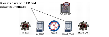
The standard model library transparently provides you with IP over FR services, without requiring any additional configuration. IP routers that act as FRADs have the intelligence to determine if the next hop they are routing to requires the traversal of an FR network. If so, the appropriate PVC is utilized to transfer an IP datagram encapsulated within one or more FR frames. FRAD models are provided and can be identified in the model library as routers with names containing the sub-string "fr". For example, the model "fr4_ethernet8_slip2_gtwy" provides four frame relay interfaces. Each interface can support an unlimited number of sub-interfaces, each of which can support a single PVC.
End-systems that can connect to the FR network directly come in two varieties. Those that contain a TCP/IP stack, and those that are simple traffic generators over FR. The devices without a TCP/IP stack are called "UNI" (user network interface) clients, while those with a TCP/IP stack are simply called "fr_wkstn" and "fr_server", as well as the advanced and intermediate versions of these devices. End-systems without the TCP/IP stack will not be able to communicate with other systems unless they are directly connected to the same FR mesh. This is the due to the fact that they provide no routing support beyond what FR offers, and so the payloads transported by the FR network have no further address information once delivered.