Reachability Analysis
To analyze a routing failure, you must verify route propagation on each node along every possible physical path. Reachability Analysis does this in one step for every path in the network.
Reachability Analysis makes it easier to analyze a routing failure to a specific destination. It searches the routing tables generated as a result of a discrete event simulation or a flow analysis, or imported forwarding tables from the operational network. For every router, it displays an arrow showing the next hop for the address you specify. As a result, you can see what paths data can take to reach the destination you specified. Gaps in the path are immediately visible as missing arrows, letting you start your investigation as closely as possible to the problem node.
Reachability Analysis even displays next hops that are not physical neighbors. By default, it also displays next hops for aggregated addresses that include the destination address. You can use Reachability Analysis for "what if" scenarios, too, such as checking whether a new router's address will be properly propagated throughout the network.
Reachability Analysis Preferences
Use Layer 3 Graph to Resolve Next Hop
When resolving the next hop of a route entry, Reachability Analysis might need to use the network model Layer 3 graph to determine the connected next hop of a node. If this preference is FALSE, then Reachability Analysis will terminate the route at the node instead of trying to resolve it further.
Do Not Consider Hosts as End Nodes
When the last hop of a route is an end-host in the model, Reachability Analysis can terminate the route at the end-host itself or at the last hop router before the host. This feature requires that the Use Layer 3 Graph to Resolve Next Hop preference is set to TRUE.
Create Debug Log Entries
When the last hop of a route is an end-host in the model, Reachability Analysis can terminate the route at the end-host itself or at the last hop router before the host. This feature requires that the Use Layer 3 Graph to Resolve Next Hop preference is set to TRUE.
Consider Global Instance IPv4 Forwarding Tables
When reading device forwarding tables, if this preference is set to TRUE, Reachability Analysis will read global instance forwarding tables.
Routing Protocols Whose Tables Should Be Considered
When the preference "Tables to Parse (Full / Per-Protocol)" is set to import specified per-protocol tables, specify the protocols whose forwarding tables should be parsed by Reachability Analysis in this preference. This preference requires that the Consider Global Instance IPv4 Forwarding Tables preference is set to TRUE.
Tables to Parse (Full / Per-Protocol)
Import from NetCollector and eXpress Data Import support the import of full forwarding tables as well as per-protocol forwarding tables. Certain analyses require the full forwarding table, while others can use any available route entries. This preference requires that the Consider Global Instance IPv4 Forwarding Tables preference is set to TRUE. Use the following values to configure how Reachability Analysis will parse available forwarding tables:
- 0—(default) Import full forwarding tables
- 1—Import any available non-overlapping forwarding tables
- 2—Import any available non-overlapping per-protocol forwarding tables
- 3—Import specified per-protocol forwarding tables. Specify the list of protocols in the preference "Protocol Tables to Parse".
Consider VRF IPv4 Forwarding Tables
If this preference is set to TRUE, Reachability Analysis will read VRF IPv4 forwarding tables. Set the preferences Routing Protocols Whose Tables Should Be Considered and Tables to Parse (Full / Per-Protocol) in the Reachability Analysis VRF IPv4 Forwarding Tables preference group when you set this preference to TRUE.
VRF Grouping
In operational networks, PE's identify the VRF table to be used for route lookup based on the MPLS tag with which the packet was forwarded. The forwarding tables do not contain this information, so Reachability Analysis must use other methods for identifying the VRF to be used. Specify the method you want to use, as follows:
- 0—Use VRF name matching
- 1—Use VPN ID matching
- 2—Use VPN ID matching, but fallback to VRF name matching when VPN IDs are not configured
VRFs Whose Tables Should Be Considered
When the preference Consider VRF IPv4 Forwarding Tables is set to TRUE, use this preference to specify the VRFs whose tables should be parsed. Set to "<ALL>" to consider all VRFs with forwarding tables, or specify VRFs as a string.
Procedure 44: Preparing to Run a Reachability Analysis
-
Enable Reachability Analysis by selecting the Protocols > IP > Routing > Enable Reachability Analysis… menu item.
Note: Reachability Analysis will not work properly if any IP addresses are set to Auto Assigned. If you need to have your IP addresses auto-assigned, choose Protocols > IP > Addressing > Auto Assign IP Addresses before running Reachability Analysis.
-
Run a discrete event simulation or a flow analysis or import forwarding tables from the operational network.
End of Procedure 44
Procedure 45: Running a Reachability Analysis
-
Choose Protocols > IP > Routing > Reachability Analysis > <source>.
Where: <source> is one of either
- Using Flow Analysis Forwarding Tables…
- Using DES Forwarding Tables…
- Using Operational Forwarding Tables…
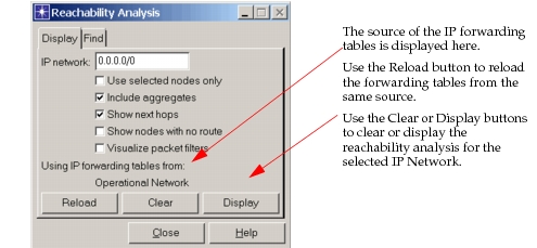
Result: The Reachability Analysis dialog box appears.
-
Specify an IP network and prefix length.
-
Specify whether to Use selected nodes only. For this choice, you must have selected one or more objects in the network model.
-
Specify whether to Include aggregates, which will show next hops for routers that have the destination address contained in aggregated addresses.
For example, if your destination address is 192.80.5.0/24, an aggregated address for that network would be 192.80.0.0/16. Routers with next hops to 192.80.0.0/16 would be included in the display if you select Include aggregates. If Include Aggregates is not selected, only next hops for routers that have the exact destination address are shown.
-
Specify whether to Show next hops.
If this box is not checked, no next hop arrows appear, only a colored letter on each router indicating the protocol that inserted the routing information. Note that if you have any nodes selected, only next hops for the selected nodes will be displayed. To see all next hops displayed, be sure that no nodes are selected.
-
Specify whether to Show nodes with no route.
When you select this checkbox, do not select Include Aggregates. If a node has no route, the node is indicated in the model with an "NR" icon.
-
Specify whether to Visualize packet filters.
When you select this checkbox, an icon is displayed that indicates whether packet filters have been configured on router interfaces.
-
Click on Display. If there are problems in running Reachability Analysis, you may see the following:
- No action—Indicates that no routes were found.
- Error—Indicates that your selection includes a Malformed IP address or that Address does not exist. The error displays at the bottom of the frame of the dialog box.
Note that if you made any topology changes after running your simulation, you must run the simulation again to generate new data for Reachability Analysis.
End of Procedure 45
Figure 209: Running a Reachability Analysis
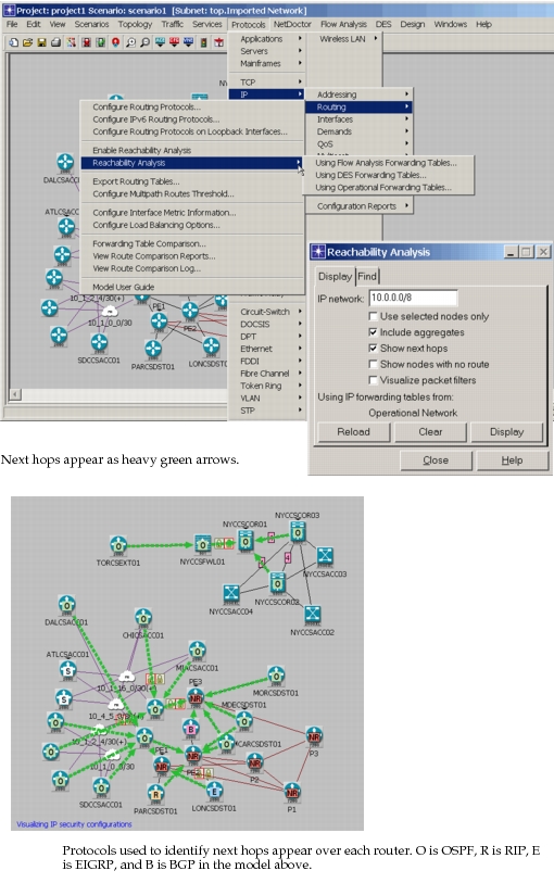
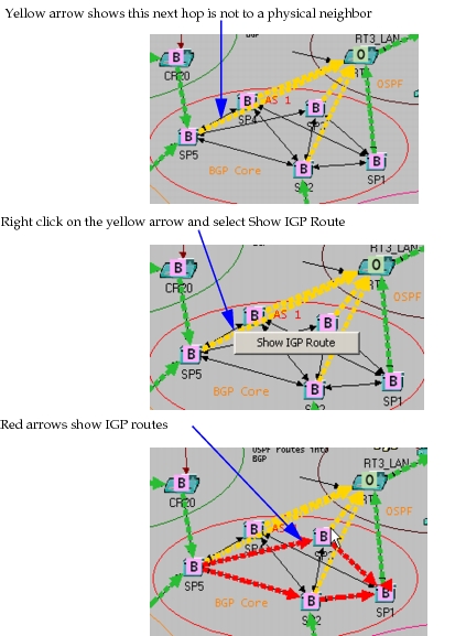
Next hops with a physical connection appear as green arrows. Next hops for BGP routes appear as yellow arrows, since the next hop node need not be a physical neighbor. The letters on the routers represent the protocol or source that informed the router of the destination address route. Protocol and source abbreviations that appear on the display are shown in the following table.
Table 108: Legend for Reachability Analysis Icons
| Letter on Router | Protocol or Source |
|---|---|
| B | BGP |
| D | Directly connected |
| E | EIGRP |
| G | IGRP |
| I | ISIS |
| L | LDP |
| NR | No route |
| O | OSPF |
| P | See Table 109 |
| Q | RSVP |
| R | RIP |
| S | Static |
 |
Originating source |
Table 109: List of Protocols or Sources Represented by the Letter 'P'
| Auto_Exported BBN Blackhole BootP CBT CLIP DownIf DownloadedStatic |
EGP ES-IS GGP Hardcoded Hello ICMP Imported Mobile |
MPLS NAT Netmgmt ODR RtAdvert SLB_VIP UserStatic |
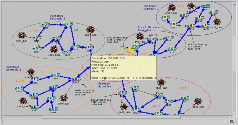
Place the cursor over an arrow to see the tooltip containing the destination address, the protocol, the address of the next hop, the insert time (of the last routing update - DES only), and the metric. The name of the path appears at the bottom of the tool tip.
Figure 210: Next Hop Descriptive Tooltip
To see the IGP routing for any BGP route shown as a yellow arrow, rest the cursor on the yellow arrow, right click and select Show IGP Route. The IGP route appears as red arrows.
Figure 211: Show IGP Route
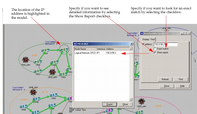
If you need to find the location of a specific IP address on your model, at any time from the Reachability Analysis dialog box you can select the Find tab in Reachability Analysis: