Configuring Network Address Translation
This section describes the workflow for setting up network address translation (NAT) on a device in the network model. There are three basic steps in the configuration:
- Step 1: Indicating the Inside and Outside Interfaces
- Step 2: Configuring the Address Translation Information
- Step 3: Assigning the Address Translation Rule to a Specific Interface
Consider the network shown in the following figure.
Figure 181: NAT Example Configuration
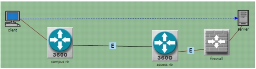
In this example, the client is attempting to reach the server across the network through a firewall. The client and the server cannot see each other via regular IP routing. NAT configuration on the firewall device helps them communicate.
Step 1: Indicating the Inside and Outside Interfaces
Under IP > NAT Parameters > Interface Information, add the interfaces that are to be set as inside and outside and configure them appropriately.
Figure 182: Set Inside/Outside Interfaces for NAT
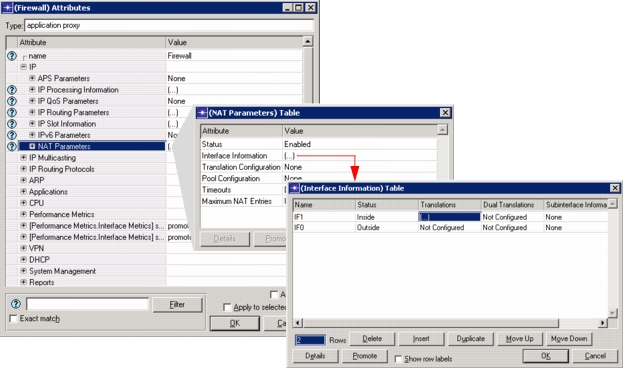
In the example shown in Figure 182, IF1 is the interface connecting the firewall to the server in the corporate network and is therefore configured as the inside interface.
Step 2: Configuring the Address Translation Information
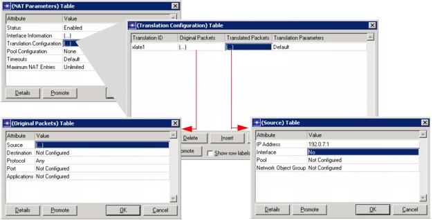
Under NAT Parameters > Translation Configuration, add a new translation that changes the source address on any traffic coming from the server (192.0.3.2) to an address on the firewall (192.0.7.1), as shown in the following figure. The firewall address is known to the outside network.
Figure 183: Configuring Address Translation Information
Step 3: Assigning the Address Translation Rule to a Specific Interface
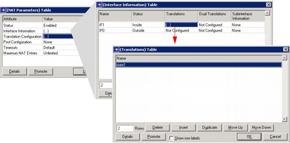
Next, you must apply this translation (in this case, xlate_1) to the inside interface on the firewall so that the source address of all packets coming from the server on IF1 will be translated. Configure this under NAT Parameters > Interface Information. On the interface to which you want to apply the translation rule, expand the Translations table. Add a row to the table, and select the translation rule from the drop-down menu, as shown in the following figure.
Figure 184: Assigning Address Translation to an Interface
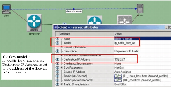
Now the network model is ready for NAT. The next phase, configuring traffic between the client and server, is as simple as configuring a flow between the devices acting as the client and servers. The only variation is that the destination of the flow should be set as the address of the firewall instead of the address of the server, as shown in the following figure. Remember the server is inside the firewall, and therefore its address is not known to the client. The client device only knows how to reach the firewall. The rest is up to the firewall to translate the traffic and forward to the server.
Figure 185: Traffic Flow with NAT