Analyzing IP Forwarding Tables
Forwarding table analysis can help you detect changes made in the forwarding tables of devices in the network. This is helpful when you want to see how the configuration changes you make in what-if analyses affect the forwarding tables. By analyzing the forwarding tables of different devices in a network, you can identify the source of problematic routing behavior.
The reports generated by the forwarding table comparison feature indicate where differences exist in the forwarding tables, but also let you know which node in the network is the source of this difference.
You can compare the forwarding tables generated from flow analysis, discrete event simulation, or the operational network (via import from NetCollector or device configuration files). The forwarding tables must be from different sources in the same scenario. In other words, you cannot compare forwarding tables from two different runs of flow analysis or from two different scenarios.
To use this feature, select the Protocols > IP > Routing > Forwarding Table Comparison… menu operation. You can configure the analysis to compare the tables from a device perspective or from a prefix perspective.
Use the following procedure to compare IP forwarding tables.
Procedure 40: Comparing IP Forwarding Tables
-
Generate forwarding table reports from the sources you want to compare.
- Operational network. You can use device configuration import or NetCollector import to import the tables from the operational network into Riverbed Modeler.
- Device Configuration Import (DCI): The tables are automatically generated during import when forwarding table information is included in the configuration files. To include forwarding table information in the device configuration files, add the output of the "show ip route" command for Cisco devices or "show route" for Juniper devices. For DCI to import the forwarding tables, the device_import.parse_ip_route preference must be set to true. This preference is set to true by default, so generally, you do not need to configure this. (Note that the preference is only visible after the Import From Device Configurations dialog box has been launched in the current session.)
- Import from NetCollector. The tables are automatically generated during import when the "Include collected configuration files" checkbox is selected in the Import from NetCollector dialog box.
- Discrete event simulation: Configure the router(s) in the network to export their forwarding tables (Protocols > IP > Routing > Export Routing Tables). Run a discrete event simulation.
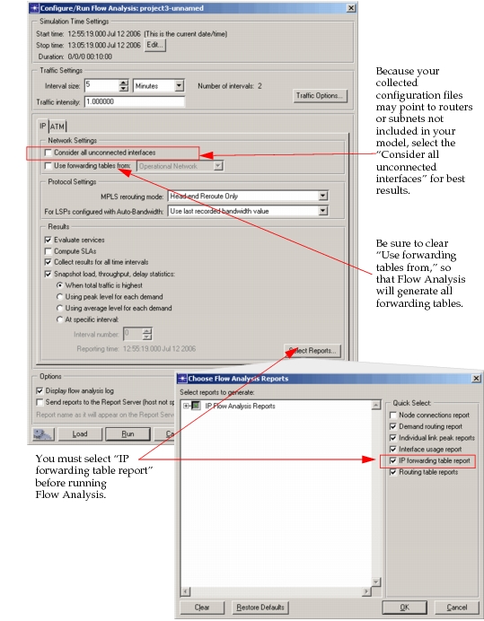
- Flow Analysis: Configure Flow Analysis to generate the IP Forwarding Table Report (Select Reports button in the Configure/Run Flow Analysis dialog box). By default, flow analysis considers only connected interfaces. You can select the Consider Unconnected Interfaces checkbox to include those interfaces in the forwarding table report. Run flow analysis.
Figure 188: Configure/Run Flow Analysis
- Operational network. You can use device configuration import or NetCollector import to import the tables from the operational network into Riverbed Modeler.
-
Select Protocols > IP > Routing > Forwarding Table Comparison.
2.1 Specify the type of analysis you want to do.
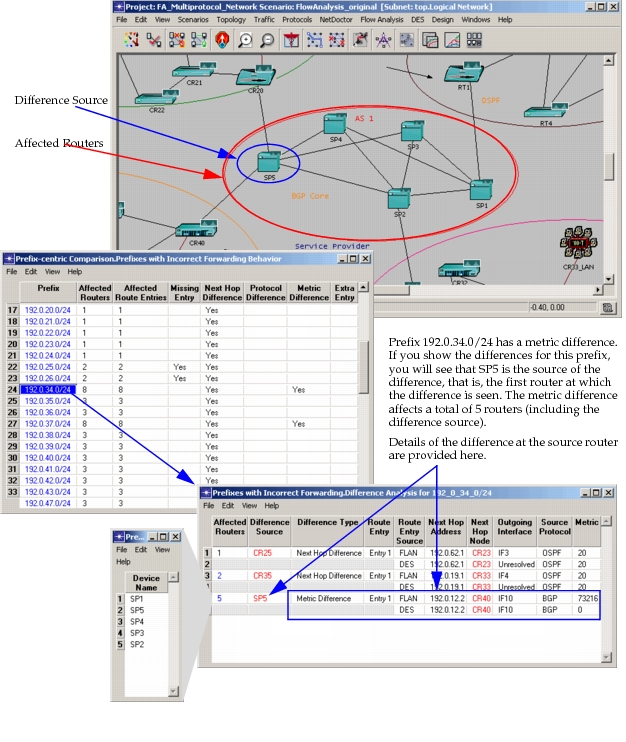
- Prefix-centric comparison across all devices—Compares each destination network or subnetwork prefix in the source of comparison (for example, discrete event simulation or flow analysis) against each destination prefix in the original source (for example, operational network). This information is presented as a whole for the network on a per-prefix basis and can be used to help you debug the network model to find the source of the differences. The source, in this case, is the first router in the control plane which shows the difference, while the difference on the other routers was learned from that node under normal route propagation. This report is helpful for debugging the model. **Figure 189: Example of a Prefix-Centric Comparison** 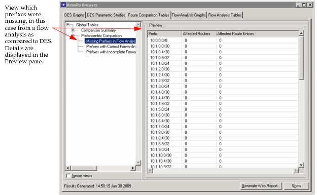 - Device-centric comparison—Compares the forwarding tables from the source of comparison (for example, discrete event simulation or flow analysis) against the forwarding tables from the original source (for example, operational network) device by device. The information is presented on a per-device basis, comparing the two sources of prefix entries for only that device. This report is helpful when you want to find specific differences for a device. **Figure 190: Example of a Device-Centric Comparison** 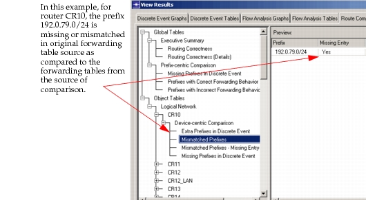- Both Prefix-centric and Device-centric comparison—Prepares reports for both types of comparison, previously described.
-
Specify filters to narrow the scope of the comparison, if you want to study a sub-set of your network model (i.e., if you want to examine only routers containing the word CORE).
Note: Use the "Help" button on this dialog box for further assistance in using filters.
Figure 191: IP Forwarding Table Comparison Dialog Box
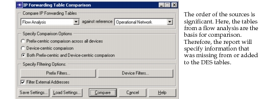
3.1 Click the Prefix Filters… or Device Filters… button.
3.2 In the Device selection section, click on the drop-down box and select "Use Include List", "Use Exclude List", or "Select All".
**Figure 192: IP Forwarding Table Device Filters Dialog Box** 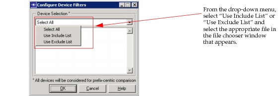 **Figure 193: IP Forwarding Table Prefix Filters Dialog Box** 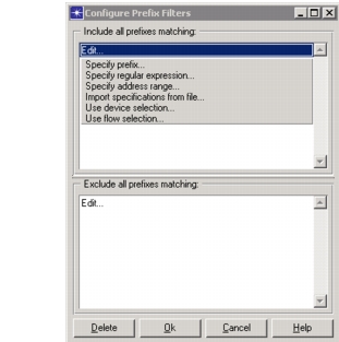3.3 Click OK.
-
Click Compare.
-
Examine the reports.
5.1 Right-click in the project workspace, and click View Results to open the View Reports dialog box. Select the Routing Table Comparison tab.
**Note:** If you want to see the Device-Centric report, right-click on the device in which you are interested and select View Results.5.2 Select the report you want to view from the treeview then click Show to display the report.
**Figure 194: Summary Report for a Forwarding Table Comparison** 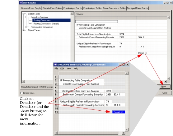 **Note:** If you want to run additional comparisons, do not close the IP Forwarding Table Comparison Dialog Box between runs. The tables are kept in memory until the dialog box is closed—keeping the dialog box open saves you from waiting for the tables to be reloaded each time.
End of Procedure 40
Using Forwarding Table Analysis for Debugging
Routing validation can be useful in debugging your network model to determine differences between routing behavior in your operational network versus routing behavior in your simulations. Differences that occur between forwarding table sources can happen for several reasons. For example
- A feature or attribute may be unsupported in Flow Analysis or DES. To determine if a feature is supported, search for "Supported Vendor Protocols and Commands" on the Support website: support.riverbed.com.
- A feature or attribute may be unsupported by import and, therefore, may not be parsed. For more assistance, search for "Supported Vendor Protocols and Commands" on the Support website: support.riverbed.com.
Sources of Differences
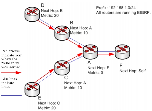
The following figure shows two versions of the same network model. In the first version of the model, the routing behavior of the operational network shows the metrics and the next-hop routers as traffic tries to reach router F and prefix 192.168.1.0/24. These are the metrics present in the operational network forwarding tables.
Figure 195: Routing Behavior in the Operational Network
In the second version of the model, the routing behavior simulated by Flow Analysis is different because of a metric difference in router A. This difference propagates to all other routers learning of the entry from router A, therefore affecting four other routers.
Figure 196: Routing Behavior in Flow Analysis – Differences in Comparison
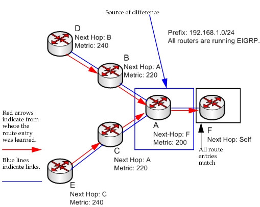
The source of the routing difference is router A. Since router A forwards information about prefix 192.168.1.0/24 to its neighbors, if you correct the problem in router A, the problem will be corrected on the downstream routers.
Report Example
Routing validation compares the forwarding tables generated by a simulation, Flow Analysis or DES, against the forwarding tables learned from another source: operational network, Flow Analysis, or DES. Three items are compared and reported: next-hop router, protocol, and metric. Additionally, when Flow Analysis is compared against another source, missing entries or extra entries in Flow Analysis are included in the report.
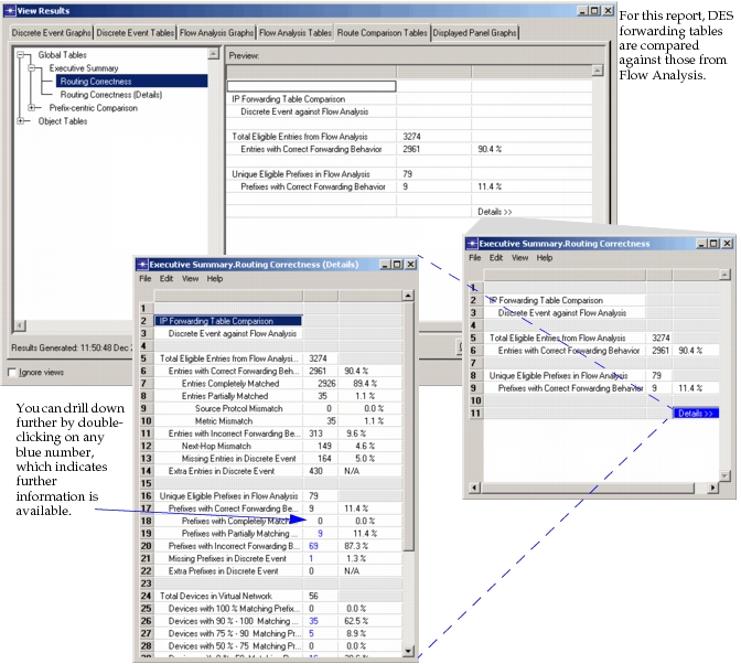
In the following example of an Executive Summary from a report of 3274 route entries in the network
- 90.4% of the route entries will have correct forwarding behavior, although in some cases the metrics did not match.
- 9.6% of the route entries will not have correct forwarding behavior due to mismatched next-hop or missing route entries.
- There are 430 extra route entries in DES as compared to Flow Analysis.
- There are 56 devices in the network model.
- There are 79 unique prefixes among the Flow Analysis route entries.
Figure 197: Executive Summary for Prefix-Centric Report
A breakdown, by prefix, of correct or incorrect routing behavior is available.
Figure 198: Prefix-Centric—Analysis of Routing Behavior
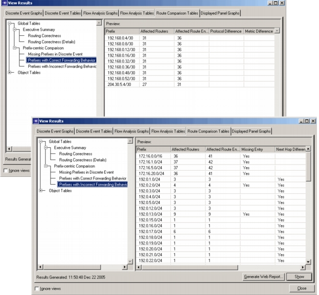
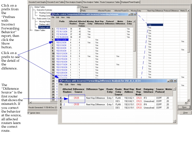
As illustrated below, you can select a prefix for which a difference exists and click on the Show button for more information. In this example, you can see that there is a next-hop difference for prefix 192.0.1.0/24. When you expand the details, you can see that there are two difference sources, CR25 and CR35. Together these difference sources affect three routers. This report helps you to define the source of the next-hop difference. You can use this information to troubleshoot the reason for the difference at the source routers.
Figure 199: Detail of Next Hop Difference
Some reports provide expandable tables for more information. The report shown in Figure 200 provides three source routers at which you can begin troubleshooting the missing prefixes. When you correct the problem at the router which is the source of the difference, the change will correct the behavior in all affected routers.
Figure 200: Detail of Missing Prefixes
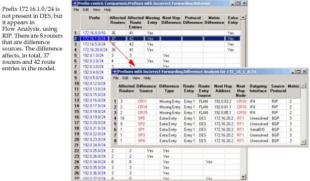
Figure 201: Detail of Metric Difference