Troubleshooting MPLS Network Configurations
This section covers some configuration problems that you might encounter while configuring MPLS network models.
Unroutable LSPs
When you show LSP routes after a discrete event simulation or flow analysis, some of the LSPs might be unroutable. The flow analysis Failed LSP report might also indicate that one or more LSPs are unroutable. When this occurs, you can determine the cause of an unroutable LSP by checking the following common causes:
- Loopback interface not configured with routing protocol. Make sure that the source and destination nodes of the LSP have the routing protocol properly configured for the loopback interfaces.
- IGP routing protocol not configured. The IGP routing protocol may not have a route for the source-destination pair of the LSP. Check the routing tables to make sure that a route exists.
VRF Tables Not Built Correctly
There are two main causes of VRF tables not being built correctly:
- No VRF on PE. If there are no VRFs configured on the PE node, first check the VRF configuration. Next, check the PE-CE routing protocol and adjacency.
- No remote peer routes in VRF. First, check the internal BGP configuration under VPNv4 address family. Next, make sure that the send community is enabled. Finally, make sure that there are LSPs on LDP paths between PE routes.
Verifying Inter-AS VPN Configurations
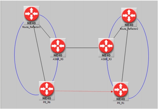
To troubleshoot inter-AS VPNs, verify the configurations, as described in this section. In the following example, two autonomous systems are configured to use the option C method for inter-AS Layer-3 VPN. PEs and ASBRs are iBGP peers to route reflectors within each AS. ASBRs are eBGP peers. All of these BGP connections exchange IPv4 prefixes along with labels. The IPv4 prefixes advertised between ASBRs are the loopback interfaces of the route reflectors (RR) and PEs. Once all PEs and RRs can communicate with each other, the PEs or RRs can set up a direct MP-eBGP session and exchange VPNv4 (for IPv4) or VPNv6 (for IPv6) information. VPNv4/6 prefixes are advertised along with VRF labels, with PEs as the next-hops. Finally, a labeled path is used to reach a destination PE in another AS from a source PE in one AS.
Figure 410: Inter-AS VPN using Option C
Procedure 99: Example: Troubleshooting an Inter-AS VPN
-
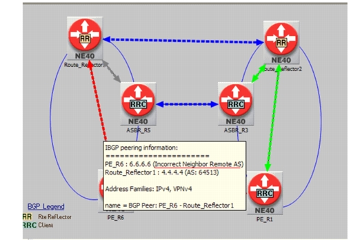
Check BGP peering by choosing View > Visualize Protocol Configuration.
Figure 411: Visualizing BGP Configuration
-
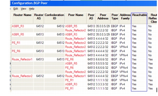
Fix BGP configuration and Run Flow Analysis, selecting the BGP Peer report to see reachability.
Figure 412: BGP Peer Reachability
-
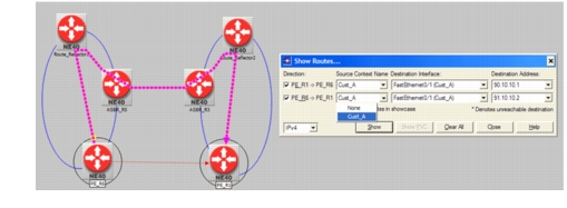
Select the PE devices and show route between VRF interfaces
Figure 413: Show Routes for VRF Interfaces
-
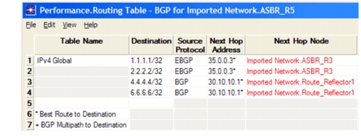
Check BGP Tables of ASBR for Global table. They contain the loopback interface prefixes of Route Reflectors and that of PEs.
Figure 414: View BGP Tables
-
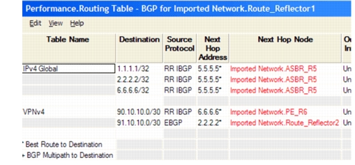
Check BGP Tables of Route Reflectors or PE nodes for VPNv4 table. They contain prefixes of VRF interface facing customer sites.
Figure 415: Check BGP Tables of Route Reflectors
-
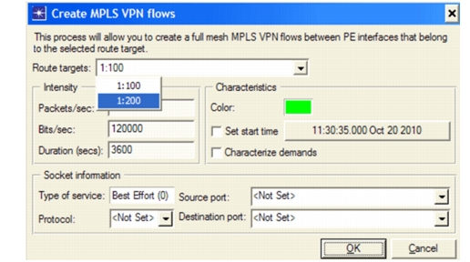
Create MPLS VPN flows among PE nodes to test traffic routability by choosing Traffic > Create Traffic Flows > MPLS VPN....
Figure 416: Create MPLS VPN Flows
End of Procedure 99
You can also review the following Flow Analyses reports to study traffic performance:
- Performance.Demand Routing
- Performance.Failed Demands - Unroutable