Facility Backup Using Bypass Tunnels
Facility backup creates a bypass tunnel to protect a potential failure point. This section describes how to
- Configure a bypass tunnel
- Set bandwidth quotas
Configuring Bypass Tunnels
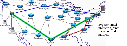
A bypass tunnel protects an interface on a point of local repair against downstream link/node failures. Procedure 87 describes how to set up bypass tunnels.
Figure 395: A Bypass Tunnel
Procedure 87: Configuring a Bypass Tunnel
-
Open the Attributes dialog box for the node at the start of the bypass tunnel.
-
Open the MPLS > MPLS Parameters > Interface Information > Bypass Tunnel Configuration attribute.
-
Set the LSP Name to the name of an LSP that should be used as a bypass tunnel in the event of a node or link failure.
-
Click OK to close the attribute dialog box(es).
End of Procedure 87
Setting Bandwidth Quota
You can configure bandwidth protection that lets you limit the amount of bandwidth used for bypass tunnels. With bandwidth protection, the total bandwidth used by all LSPs using a bypass tunnel cannot exceed the bandwidth quota of the bypass. When assigning bypass tunnels, there must be sufficient backup bandwidth.
You can set the bandwidth quota used for facility backup by configuring the Minimum Bandwidth attribute in the LSP’s TE Parameters attribute.