Creating the LTE Topology
LTE topologies cannot be created using the import features in the software (such as import from NetCollector or device configuration files). You must create these topologies with the Wireless Network Deployment Wizard, as described in Deploying an LTE Network Automatically, or manually, as described in Manual LTE Network Creation.
Deploying an LTE Network Automatically
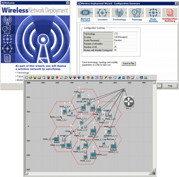
The preferred method for deploying LTE or other wireless technology-based networks is by using the Wireless Network Deployment wizard. The wizard lets you build, configure, and deploy your wireless network segments quickly and easily.
Note: For a full description of the Wireless Network Deployment Wizard, its usage and capabilities, see “Wireless Network Deployment” on page 39 of the Wireless Module user guide.
Figure 329: Wireless Network Deployment Wizard
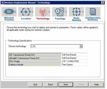
In the Technology screen of the wizard, select LTE as your wireless technology. You can then specify the following parameters (shown in Figure 330):
- UE Transmission Power (W) – Provide the transmission power (in wattage) to use for each UE
- eNodeB Transmission Power (W) – Provide the transmission power (in wattage) to use for each eNodeB
- PHY Profile – Provide the PHY profile that will be used by the deployed LTE network
- Pathloss Model – Choose the Pathloss Model to use for each UE. This will also set the Shadow Fading Standard Deviation.
Figure 330: LTE Technology Specification in Wireless Network Deployment Wizard
Manual LTE Network Creation
When you create the network model, you can specify certain characteristics such as the geographic size of the model. Creating a network topology for LTE is similar to creating any other network topology. Be aware that to set geographic size for the model, you must select the following in the Startup Wizard:
- Initial Topology – Choose Create Empty Scenario
- Choose Enterprise, Campus, or Office. You are prompted for dimensions.
You can add nodes to your network model several ways:
- Manually, by dragging and dropping objects from the object palette into the Project Editor workspace.
- Manually, using the Topology > Rapid Configuration... command from the menu bar to specify and build a complete network topology quickly.
- Programmatically – You can use the OPNET Development Kit to add nodes to a network model. For more information about this option, see Ets_Obj_Install(). You can also use External Model Access (EMA) to add a number of nodes to a model. For more information about this option, see External Model Access.
Supported LTE Topologies
The following LTE topologies are supported:
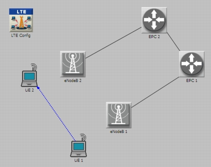
- An eNodeB node can communicate with one or more UEs and with one or more EPCs
- An EPC node can communicate with one or more eNodeBs
- Applications can be configured to communicate UE to UE, UE to external network, and external network to UE
Figure 331: LTE Topology with Communication to External Network
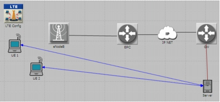
Figure 332: LTE Topology with Multiple eNodeBs and EPCs
Support for UMTS Networks
Support is also provided for EPCs to connect to serving GPRS support nodes (SGSN) in place of a gateway GPRS support node (GGSN). This provides legacy support to UMTS networks, while letting you model end-to-end application performance through 3G and 4G networks. Note the following in regard to configuration:
- UMTS networks support only one GGSN node in the simulation network model. Therefore, if an EPC is connected to a UMTS network to serve as a GGSN, only one EPC node will be allowed in the whole network.
- Set the “GGSN ID” attribute on the SGSN to the EPC ID of the serving EPC
- SGSN ID numbers must be unique from the EPC ID. That is, if an EPC ID is “0”, no SGSN can use the ID of “0”.
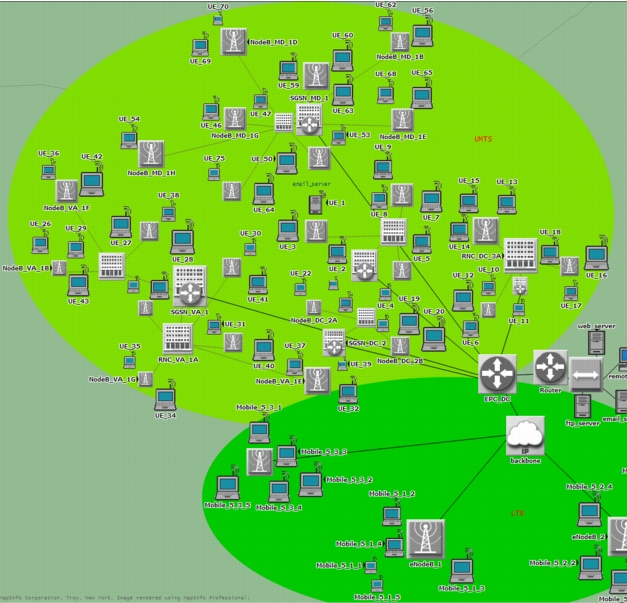
Notice in the figure below that a single EPC serves eNodeBs in the LTE network and SGSNs in the UMTS network simultaneously. Only one EPC is allowed in this type of topology, as described above.
Figure 333: LTE and UMTS in a Network Model
For more information about UMTS networks, see “UMTS” on page 1.