EPS Session Management (ESM)
The following topics are covered in this section:
EPS Bearer Creation/Activation
The EPS bearer creation/activation is modeled based on Figure 5.4.1-1: “Dedicated Bearer Activation Procedure” in 3GPP TS 23.401, “General Packet Radio Service (GPRS) enhancements for Evolved Universal Terrestrial Radio Access Network (E-UTRAN) access”. If the UE wants to trigger creation or activation of a bearer, the UE communicates with the PCRF entity in the EPC node using an ESM Bearer Resource Modification Request message, and from that point on, the same procedure is executed to create or activate the requested EPS bearer.
The procedure used to deactivate GBR-type EPS bearers and their radio bearers is implemented based on Figure 5.4.4.2-1: “MME initiated Dedicated Bearer Deactivation Procedure” in 3GPP TS 23.401 “General Packet Radio Service (GPRS) enhancements for Evolved Universal Terrestrial Radio Access Network (E-UTRAN) access”. The procedure is initiated by eNodeBs. An eNodeB deactivates a GBR bearer and frees its radio resources either due to inactivity of the bearer or to admit a higher priority GBR bearer (for example, because of preemption triggered by admission control).
GTP Tunneling Between eNodeB and EPC Nodes
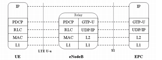
GTP tunnels carry the EPS bearers in the core network. A GTP tunnel is dynamically established for each EPS bearer.The GTP layer is located at the eNodeB and EPC nodes as shown below:
Figure 314: GTP Tunneling Between eNodeB and EPC Nodes
IP datagrams are sent through the corresponding GTP tunnels in the LTE core network with encapsulation headers as illustrated in the figure below.
Figure 315: IP Datagram Encapsulation Over GTP Tunnel

- The IP ToS value for the outer IP header inside the GTP tunnel is inherited from the IP ToS value of the original IP datagram sent by the user (that is, the value contained in the inner IP header).
- GTP-C is used instead to model the control plane between the UE, eNodeB, and MME (S1-C interface). A pair of GTP tunnels (one uplink and one downlink) is therefore established between the eNodeB and EPC for each UE that is registered in the network in order to carry the management messages to and from that UE.
- The S1-TEID uniquely identifies a GTP tunnel, and due to one-to-one mapping between S1-TEIDs and RB-IDs, the S1-TEID also forms the association between a GTP tunnel and its radio bearer (RB-ID)