Hybrid Automatic Retransmission Request (HARQ)
HARQ is supported for both uplink and downlink. HARQ support is described in this section.
- Features Common to Uplink and Downlink Support
- HARQ Downlink Support
- HARQ Uplink Support
- Other Model Features
Features Common to Uplink and Downlink Support
The following features are supported in the LTE model for both uplink and downlink:
-
Packet Combining – Type II incremental redundancy is supported. To find the SNR and coding gains, we first give the formula for calculating the SNR gains using chase combining only:

Where:
- SINRᵏ denotes the SINR of the packet after combining k retransmitted copies
- and SINR(i) denotes the SINR of iᵗʰ retransmitted copy
For type II incremental redundancy, we assume that the "additional" bit carrying capacity in transport blocks is used by the parity bits, which provide an extra SNR gain at the receiver. If there are no parity bits, no extra SNR boost is observed, and we get the same gain as in the Chase combining. Thus, type II incremental redundancy performs at least as good as the chase combining in all cases.
The total gain at the receiver is shown below:

-
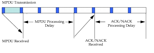
Processing Delays – Each received packet experiences a processing delay. According to the LTE standard, we assume a constant processing delay of 3 subframes for received MPDUs and the same delay of three subframes to process HARQ ACKs/NACKs in both the uplink and the downlink (see Figure 322). For FDD, the HARQ round trip time (RTT) is 8 subframes as shown below. For TDD, the HARQ round trip time depends upon the TDD frame type and the subframe in which the transmission scheduled. The processing delays are assumed to be “at least” 3 subframe for TDD.
Figure 322: MPDU Transmission
-
Multiple HARQ Processes – The UE supports multiple HARQ processes to enable parallel transmission for uninterrupted communication.
-
Protocol Constants – For FDD physical profiles, at most eight parallel HARQ processes are required for uninterrupted communication to the UE, as shown in the figure below. For TDD, the number of HARQ processes is different for uplink and downlink for each TDD frame type as given in the following table.
Table 147: Number of HARQ Processes for Each TDD Frame Type
Index Uplink Downlink 0 7 4 1 4 7 2 2 10 3 3 9 4 2 12 5 1 15 6 6 6
HARQ Downlink Support
In addition to support common to both direction, the downlink features supported in the model are as follows:
-
Downlink HARQ transmission on LTE channels
- HARQ Process Selection – In downlink mode, an unblocked HARQ process must be found on which to transmit the data. Once an HARQ process is selected, it is signaled on the PDCCH to associate it with the corresponding MPDU(s).
- Multi-Codeword Spatial Multiplexing – If the UE is capable of supporting spatial multiplexing, each HARQ process is then capable of transmitting two codewords simultaneously.
-
Downlink HARQ scheduler at the eNodeB
- Downlink Scheduler Sequence – The downlink scheduler adheres to the following order: a) Random access response messages, b) CCCH messages, c) All HARQ retransmissions, and d) All new data transmissions.
- Dynamic Retransmissions – All retransmissions are scheduled dynamically. A DCI is created on PDCCH to signal the HARQ process ID for the retransmission element.
Note: Retransmissions are adaptive, and although adaptive modulation and coding is supported, retransmissions by default use the same MCS index as the original transmissions.
-
HARQ transmission on LTE channels
-
MPDU Transmission – HARQ MPDUs are transmitted on PDSCH. Control information is signaled on PDCCH. The following information is signaled: HARQ process identifier (three bits), New Data Indicator (one bit), Redundancy Version (two bits).
If multi-codeword spatial multiplexing is used, then the above information will be available in PDCCH for each of the two codewords transmitted. If multi-codeword spatial multiplexing is used, then two ACK/NACK bits, one per each codeword, will be generated; otherwise only one ACK/NACK bit will be generated as the response to HARQ transmissions.
-
Acknowledgements – Downlink HARQ ACKs are either sent on PUCCH or multiplexed with uplink data on PUSCH. For TDD, multiple downlink HARQ processes can be ACKed by a single ACK bit per codeword on the uplink. This scheme is called ACK bundling. Table 10.1-1 in standard [36.213] details which HARQ transmissions are ACKed on the current uplink subframe. In the worst case (for TDD index 5), up to nine downlink MPDUs can be ACKed by a single bit.
-
Attributes – Maximum Number of Retransmissions (allowable values: 1-9, default: 3).
-
HARQ Uplink Support
In addition to features common to both directions, the uplink features supported in the model are as follows:
- Uplink HARQ transmission on LTE channels
-
Attributes – Maximum Number of Retransmissions (allowable values: 1-9, default: 3).
-
HARQ Process Selection – In uplink, the HARQ process ID is implicit and is not signaled on PDCCH. The process ID (for FDD) is calculated as follows:
10*frame_number + subframe_number modulo 8 -
For TDD, since the number of HARQ processes is different from 8, the process ID is not calculated using the formula above. Rather it is obtained using a static table lookup that is a function of the current subframe number. For the cases of TDD index 0 or 6, the HARQ process ID also depends upon the current frame number.
-
- MPDU Transmission – HARQ MPDU is transmitted on PUSCH. If control information needs to be signaled, it is signaled on PDCCH. In the latter case, the following information is signaled: New Data Indicator (one bit), Redundancy Version (two bits).
- Uplink HARQ scheduler at eNodeB
-
Persistent/Synchronous Retransmissions – On uplink, only synchronous mode is supported. This means an initial transmission determines all future retransmissions in advance. All retransmissions occur after eight subframes, and if TTI bundling is enabled, retransmissions occur after 16 subframes. Reception of an ACK on PHICH or reception of a new grant with NDI = 1 stops the synchronous retransmissions.
-
In some cases, adaptive retransmission may be performed on the uplink, in which case a new control element (DCI) is signaled on the PDCCH with the NDI bit set to 0. This DCI may carry a different location on the uplink subframe relative to the original transmission.
Uplink HARQ ACKs are sent on PHICH. Reception of a new grant (NDI = 0 stands for NACK, and NDI = 1 stands for ACK) also implicitly signals the ACK for the previous MPDU transmission and takes a higher priority over the ACK communicated via PHICH. There is no dedicated space in the frame for PHICH, rather HARQ ACK bits are modulated and spread over the entire downlink spectrum. HARQ ACKs are always sent at frame n+4, for FDD, and at frame n+k, for TDD, where k is obtained using Table 8-2, standard [36.213]. A user-specified error rate is used to model the error probability on the PHICH channel.
In particular, the downlink subframe 0 carries acknowledgments for uplink subframes 4 and 7. Also, the downlink subframe 5 carries acknowledgments for uplink subframes 9 and 3 (belonging to the next frame). An HARQ ACK that comes in one of these two downlink subframes is distinguished by a special field called the “msb bit” to help identify which uplink subframe it is acknowledging.
-
Other Model Features
-
Modeling of Errors and Drops on Control Channels – The following types of errors and drops are modeled:
- PHICH: ACK—>NACK and NACK—>ACK errors are modeled
- PDCCH: Drop probability for the DCIs is modeled separately for the uplink grants and downlink information elements.
- PUCCH: ACK—>NACK and NACK—>ACK errors are modeled
Each of these probabilities is configurable separately per cell. The relevant attributes are in LTE > L1/L2 Control Parameters on eNodeB.
-
Support for Random Access Procedure – In the random access procedure, HARQ is used on msg3 on the uplink and msg4 on the downlink. The number of retransmissions for these messages is calculated separately. For msg3, the number of retransmissions can be manually configured between 1 and 8 or can be left auto-assigned, in which case it will be calculated from the contention resolution timer as follows, where C is the contention resolution time in subframes:
