Running a Simulation for LTE
Use the following procedure to configure LTE in the network model.
Procedure 77: Configuring LTE
-
Open a new project in Riverbed Modeler, as described above.
-
Add nodes to the network model.
-
Launch the LTE object palette by clicking on the
 icon in the toolbar.
-
Select and add network elements to the model. The minimum configuration must contain the following:
- LTE Configuration node
- eNodeB
- EPC
- One or more mobile stations
-
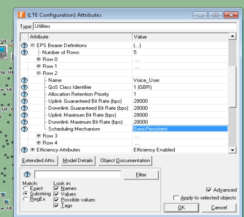
Configure LTE options on the LTE Configuration node. Modify existing or create new EPS Bearer Definitions or LTE PHY Profiles for use in configuring the model.
Figure 335: Configure LTE Options on LTE Configuration Node
-
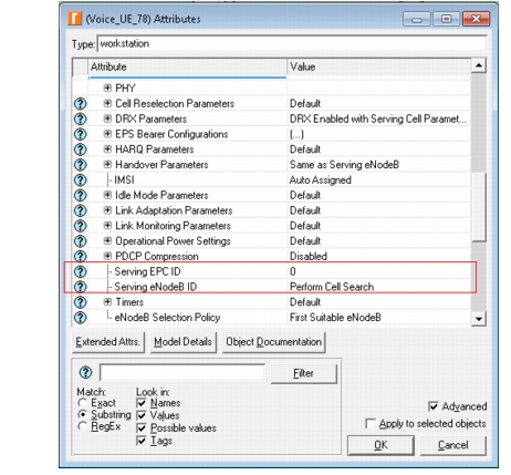
Configure the eNodeB and EPC IDs per your network configuration, as shown in the following figure. (See Attributes Affecting Cell Selection.)
Figure 336: EPC and eNodeB ID Settings
-
Set the eNodeB Selection Policy to “First Suitable eNodeB” or “Best Suitable eNodeB” per your network configuration.
-
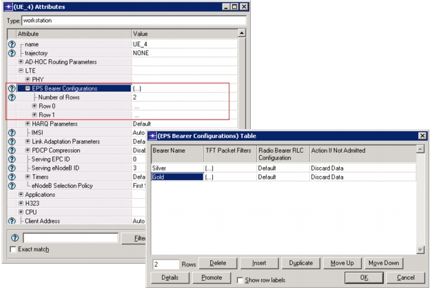
Set the EPS Bearer Definition on the mobile node(s) as shown in the following figure.
Figure 337: Set EPS Bearer Definition on Mobile Node
-
-
Add link objects from the object palette to establish connectivity between nodes (i.e., 100BaseT link from Ethernet link models).
-
Configure traffic in the network model.
Note: Only explicit traffic demands are supported. Background traffic is not supported.
-
Run a discrete event simulation.
End of Procedure 77