Medium Access Control (MAC)
This section describes LTE model support for the MAC layer and includes the following sections:
- Channel Mapping
- Random Access Procedure
- Scheduling Requests
- Buffer Status Reporting (BSR)
- Frame Generation and Scheduler
- Channel Dependent Scheduling
- Semi-Persistent Scheduling
- Discontinuous Reception (DRX) in Connected Mode
Channel Mapping
- Mapping of EPS/radio bearers into logical channels is performed
- Mapping of logical channels into transport channels is performed
The following table shows the logical channels that are modeled together with their transport channels and usage:
Table 141: Mapping of Logical Channels to Transport Channels
| Direction | Logical Channel | Transport Channel | Usage |
|---|---|---|---|
| Downlink | Common Control Channel (CCCH) | Downlink Shared Channel (DL-SCH) | Control messages sent before UE's RRC connection |
| Dedicated Traffic Channel (DTCH) | Downlink user data | ||
| Dedicated Control Channel (DCCH) | Downlink control information | ||
| Uplink | Common Control Channel (CCCH) | Uplink Shared Channel (UL-SCH) | Control message sent before RRC connection |
| Dedicated Traffic Channel (DTCH) | Uplink user data | ||
| Dedicated Control Channel (DCCH) | Uplink control information |
The “starting” modulation and coding rate of the UE for both DL-SCH and UL-SCH is determined by the “Modulation and Coding Rate” attribute configured on the UE. If the simulation is run in the efficiency mode “PHY Disabled”, this MCS index does not change during the simulation duration. Otherwise, the MCS index for each UL-SCH and DL-SCH adapts itself depending upon the channel conditions.
- MCS index values and their mapping to TBS indices are based on table 7.1.7.1-1 for PDSCH and table 8.6.1-1 for PUSCH in [36.213]
- The transport block size, in bits, is determined by applying the TBS index (ITBS) and the number of transport blocks (NPRB) in table 7.1.7.2.1-1 of [36.213]
Between each UE and its eNodeB, SRB0 and SRB1 are the radio bearers of CCCH and DCCH, respectively. There is a separate radio bearer for the Default bearer and each active EPS bearer.
Random Access Procedure
Random access procedure is implemented as follows:
- A UE MAC uses random access procedure to send CCCH messages to eNodeB until the setup of the RRC connection during the network attachment is complete, and to send buffer status reports to eNodeB if the UE does not have any slot assigned on PUCCH to transmit scheduling requests.
- Number and format of random access (RA) preambles, number of RA resources per frame, the values of RA related timers, and maximum back-off duration are attributes of each eNodeB, and these are retrieved and used by the eNodeB's UEs.
The relevant attributes are in LTE > Random Access Parameters on eNodeBs. For TDD mode, the set of random access parameters configurable for each type of physical profile is restricted. If you configure random access attributes that cannot be used for the given TDD physical profile, the parameters are changed internally and a DES log message notifies you of the change.
Scheduling Requests
A UE MAC can make Scheduling Request (SR) transmissions in order to request UL-SCH resources for new uplink transmissions when the surrounding UE has slots assigned on PUCCH for this purpose.
Buffer Status Reporting (BSR)
Buffer Status Reporting is configurable on eNodeB in the following compound attribute: LTE > Buffer Status Report Parameters
- Short and long BSRs are supported
- Regular, periodic, and padding BSRs are implemented
- The mapping of the bearers to the four Logical Channel Groups (LCGs) for the purpose of buffer status reporting is based on the QCI values of the bearers. The QCI-to-LCG mapping is as follows:
Table 142: QCI-to-LCG Mapping for Buffer Status Reporting
| LCG | QCI Values | Description |
|---|---|---|
| 0 | 0, 5 | This LCG represents the signaling bearer (QCI 0) and the high priority non-GBR bearers (QCI 5) |
| 1 | 1, 2, 3, 4 | Used for GBR bearers |
| 2 | 6, 7, 8 | Used for non-GBR bearers, except the Default bearer |
| 3 | 9 | Used for non-GBR Default bearer |
Frame Generation and Scheduler
A common scheduler is used for the following tasks:
- At eNodeBs, while generating the MPDUs of a downlink subframe
- At eNodeBs, while creating the uplink grants for an uplink subframe
- At UEs, while filling an uplink grant with the data of active bearers
The scheduler operates based on the following main rules:
- Signaling bearers (that is, bearers carrying protocol packets) have higher priority over data bearers
- GBR bearers have priority over non-GBR bearers. One exception is that non-GBR bearers with a QCI of “5” have higher priority over GBR bearers.
- Frame capacity is expected to be sufficient to handle all the GBR bearer traffic, since their radio bearers are accepted only through admission control. The scheduling algorithm used for servicing the GBR bearers is proportional fair scheduling, which guarantees a minimum transport of the bit rate specified in the EPS bearer contract with delays below the values that are specified in Table 140. Traffic contract for an uplink logical channel group is the combination of the individual traffic contracts of its GBR bearer members. The combined bit rate is the sum of the individual bearers' bit rates. The combined delay is the minimum of the individual bearers' delays.
- The remaining frame capacity is given to non-GBR bearers. The non-GBR bearers are serviced using a fairness scheduling scheme, in which available resources are shared equally among bearers with data when they have the same QCI.
- In some cases, GBR bearers have traffic that exceeds their contract due to underestimation of RLC and MAC layer overheads or due to a higher than expected load from higher layers. In such cases, the excess traffic of GBR bearers are served by the scheduler the same way the traffic of non-GBR bearers is served but only after all the traffic of regular non-GBR bearers is handled.
- The frame generator is run in every subframe for the FDD mode. For the TDD mode, the frame generator is run only when the present subframe is downlink. Grants for future uplink subframes are signaled in the present downlink subframe. For the FDD, grants are signaled for an uplink four subframes from now. For the TDD, this is determined by Table 10.1-1 in standard [36.213].
- While creating a subframe, the frame generator at eNodeB first places configured SPS grants and implicit retransmissions into the uplink subframe, and configured SPS transmission assignments and paging messages into the downlink subframe. Then it services the pending Random Access Responses (RARs) as the highest priority by placing them into the DL subframe and creating the corresponding UL grants within the UL subframe. Queued CCCH messages are placed into the DL subframe as the second highest priority. From that point on, the scheduler is used to fill the rest of the subframes.
- Pending RARs that could not be served in the next subframe are not queued for the following subframes, and they are discarded.
- The DL subframe is shared between the Physical Downlink Control Channel (PDCCH) and the Physical Downlink Shared Channel (PDSCH). Riverbed's frame generator algorithm supports flexible resizing of the DL control channel. PDCCH can take anywhere between one and three symbol times, with the exact number depending on the number of control channel elements (CCEs) in that subframe. If PDCCH is resized to one or two symbol times, extra space is created for PDSCH, which can then be used to send more data.
- The eNodeB UL scheduler services individual uplink logical channel groups; however, allocations in a subframe for all the bearers belonging to the same UE are provided to the UE as a single uplink grant.
For more information about frame generation and scheduling as it relates to HARQ, see Hybrid Automatic Retransmission Request (HARQ).
Channel Dependent Scheduling
Channel dependent scheduling is supported. LTE uses channel variations as input to the scheduler. By taking into account the channel conditions at each time and subband, the scheduler has the option of scheduling UEs in their preferred subbands.This can improve performance for some UEs, as well as the performance of the overall cell. To perform channel dependent scheduling, eNodeB needs information of each specific subband, which the UEs provide by means of CQI feedback.
See also Channel Quality Indicator (CQI) and Link Rate Adaptation.
Semi-Persistent Scheduling
Semi-persistent scheduling (SPS) is supported for GBR bearers only. Unlike dynamic scheduling, SPS allocates resources once to the UE, whether it is an uplink grant or a downlink transmission assignment, and this resource allocation repeats with a certain period indefinitely until terminated or modified. This way eNodeB does not need to consume PDCCH resources for the repeating allocations, which makes SPS a very efficient choice for EPS bearers that carry small data packets arriving at a constant rate, such as VoIP data. The UE is given a unique SPS identifier (SPS C-RNTI) before any semi-persistent scheduling takes place. The configured SPS uplink grants and downlink transmission assignments can be terminated in one of two ways:
- Explicit Release – Using the SPS C-RNTI of the UE and a release DCI, which is a special DCI that needs to be acknowledged when it is for a downlink SPS configuration.
- Implicit Release – (Uplink only) Automatic termination after N consecutive empty transmissions.
SPS is specified as the Scheduling Mechanism for an EPS bearer on the LTE Config Node, while the Semi-Persistent Scheduling Parameters are specified on the eNodeB.
Notes:
- A UE can have a maximum of one EPS bearer that is using SPS. All transmissions to and from the UE that are scheduled using SPS will carry only the traffic of that EPS bearer.
- The scheduler will modify the configured SPS grants and transmission assignments and adjust their sizes in the number of allocation blocks when the UE's MCS index changes due to link adaptation.
- If semi-persistent transmissions cannot be scheduled for an admitted SPS bearer for any reason, dynamic scheduling will be used.
- The optional uplink SPS operation feature “Two-Intervals Configuration”, which is applicable only in case of TDD, is not supported.
Discontinuous Reception (DRX) in Connected Mode
DRX in connected mode is a power-saving method that exists in LTE. DRX is a method by which the UE can switch off its receiver for a period of time, thereby saving energy, while remaining in the RRC_CONNECTED state.
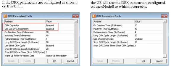
Values of DRX parameters used in a cell are advertised by the eNodeB. These values can be configured on the eNodeB under LTE > DRX Parameters. The ability to perform DRX procedures is a UE capability and is configured on the UE under LTE > DRX Parameters > DRX Capability. The model also allows UEs to use their own DRX parameters, configured under LTE > DRX Parameters instead of the ones advertised in the cell.
Note: To use the UE-specific parameters, “Use Cell DRX Parameters” must be Disabled on the UE. Otherwise the UE-specific DRX parameters are ignored, and the UE receives the DRX configuration from the eNodeB to which it attaches.
In the following example, the UE will respect the DRX parameters on the eNodeB, because “Use Cell DRX Parameters” is Enabled.
Figure 316: DRX Parameters
What Is a DRX Cycle?
A DRX cycle defines the periodicity of “On Duration” in the unit subframes, which is the time spent by a UE to scan the PDCCH for downlink packets intended for it, followed by an opportunity to sleep. There are two types of DRX cycles: short and long. The lengths of short and long DRX cycles are configured by the attributes “Short DRX Cycle Length” and “Long DRX Cycle Length”.
Timers Related to DRX Operation
When DRX in enabled on a UE, it uses several timers to manage its operation.
- On Duration timer – Specifies the length of “On Duration”. This is configured by the attribute “On Duration Timer”.
- Inactivity timer – Specifies the number of consecutive subframes that a UE will stay awake after successfully receiving a PDCCH DCI for either a new downlink MPDU or an uplink grant for new transmission. This is configured by the attribute “Inactivity Timer”. When a UE does not run the DRX cycle during the RRC_CONNECTED state, it runs the inactivity timer. The UE runs only one of these (either the DRX cycle or the inactivity timer) at all times during the RRC_CONNECTED state.
- DRX Retransmission timer – Every downlink HARQ process has a DRX retransmission timer associated with it, which specifies the number of consecutive subframes a UE will stay awake while waiting for a DL HARQ retransmission. This timer is started upon expiry of the RTT timer of the corresponding HARQ process. This is configured by the attribute “Retransmission Timer”.
- Short DRX timer – Specifies the duration of short DRX cycle usage, before starting the long DRX cycles. This is configured by the attribute "Short DRX Timer". You can delete the text within parentheses in the previous paragraph.
How Is the DRX State of a UE Determined?
The DRX state of the UE is determined by the following logic:
-
Active state – A UE is defined to be in the active state if any of the following conditions are true:
- The On Duration timer, Inactivity timer, or DRX Retransmission timer is active.
- The uplink data buffers are not empty and the UE has initiated an uplink transmission either by sending a scheduling request (SR) on PUCCH (which is pending) or by starting a random access procedure (which is not complete).
- At least one of the uplink HARQ processes has not been acknowledged.
From a power saving perspective, the active state can be further divided as follows:
- Listen state – the UE is running only the On Duration timer and no other timers, and UE does not have any higher layer packets in its queues. While in listen state, the UE scans the PDCCH for a downlink packet intended for it.
- Normal state – the UE is in active state, but not in listen state.
-
Sleep state – When the UE is not in active state, it is in sleep state.
The sleep state is the most power saving state of the UE and the normal state is the least power saving state of the UE.
DRX Operation
- A UE will begin DRX operation by starting the Inactivity timer after receiving DRX parameters including a DRX offset from the eNodeB in an “RRC_CONN_SETUP”, “RRC_CONN_REESTAB”, or “RRC_CONN_RECONFIG” message.
- After the Inactivity timer expires, the UE will start DRX cycles based on the configuration of the “Use Short DRX Cycle” attribute, even if one or more downlink HARQ processes are expecting a retransmission.
- If the “Use Short DRX cycle” attribute is set to Enabled, the UE will continue using short DRX cycles until the Short DRX timer (configured by the attribute “Short DRX Timer”) expires. If the short DRX cycles are not suspended during that period, all of the following DRX cycles will be long DRX cycles.
- If the “Use Short DRX cycle” attribute is set to Disabled, the UE will use only long DRX cycles.
- The DRX offset will be used to compute the start of the On Duration timer in a DRX cycle as specified in section 5.7 of 3GPP TS 36.321.
- When a UE receives a PDCCH DCI for a new downlink MPDU or an uplink grant for new transmission, its DRX cycle will be suspended and it will start the Inactivity timer. Each reception of a new packet will refresh the Inactivity timer. When the Inactivity timer expires, the UE will restart the DRX cycle.
- When the DRX Retransmission timer is set, a UE will wake up to receive the retransmitted packet for the HARQ process and remain awake until the DRX Retransmission timer expires. The DRX Retransmission timer provides the eNodeB scheduler with the flexibility to schedule the HARQ retransmission at a time later than the HARQ RTT expiry following the original transmission.
- Both the eNodeB and the UE will evaluate whether the uplink transmissions are complete by looking at the state of the uplink buffers, as well as the status of the HARQ processes. If the data buffers are empty and all HARQ processes have been cleared (either by ACKs or by exceeding the maximum number of transmission attempts), the uplink will be deemed cleared. At this point, the state of the UE will be determined by the status of the Inactivity timer and the DRX Retransmission timer.
- When higher layer data arrives for uplink transmission while the UE is in sleep state, the UE can either ignore the ongoing DRX cycle and start the uplink transmission process right away or it can cache the data until the sleep cycle expires. This is configured by the UE attribute “Wake Up Policy for Uplink Data”. By default, the UE starts the uplink transmission process immediately, irrespective of being in the sleep state or not.
- If the UE has at least one active Multimedia Broadcast Multicast Service (MBMS) bearer, the UE will remain awake during the subframes that are reserved for the traffic of MBMS bearers. The UE will not suspend its DRX cycle even if it receives a multicast packet over an MBMS bearer.
Power Consumption Measurement on UE
Power consumption during the UE’s operation is configurable in the following attributes under LTE > Operational Power Settings on the UEs.
- Operating Power in Normal State – Specifies the power consumption rate of the UE during the Normal state (i.e., when the UE is fully capable of transmitting and receiving). Default: 100 mW.
- Operating Power in Listen State – Specifies the operational power expenditure of the UE in Listen state, in which the UE is only scanning PDCCH to detect downlink data intended for it. Default: 40 mW.
- Operating Power in Sleep State – Specifies the power consumption rate of the UE during the sleep period of the DRX cycle (i.e., when the UE is running the DRX cycle but is not scanning or transmitting and is not capable of receiving). Default: 10 mW.
In addition, the battery capacity of a UE is used to calculate the remaining battery life on a UE (or at what time during the simulation the battery of the UE is fully consumed) in the Power Consumption Report after a simulation. To configure the battery capacity of a UE, choose LTE > PHY > Battery Capacity.
- Battery Capacity – Specifies the power capacity of the battery for a given device in watt-hours.
At the end of a simulation, output tables display the results. See Power Consumption Report for more information.