Wireless Network Deployment
The preferred method for deploying LTE, WLAN, MANET, WiMAX, TDMA, or custom wireless technology-based networks is by using the wireless network deployment wizard. The wizard lets you build, configure, and deploy your wireless network segments quickly and easily.
Figure 19: Wireless Network Wizard
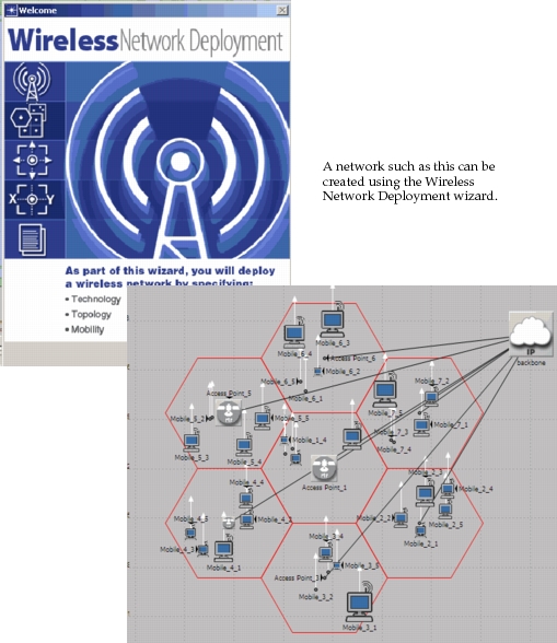
The following procedure describes the use of the wizard.
Procedure 14: Deploying a Wireless Network with the Wizard
-
Open a project or start a new blank project.
-
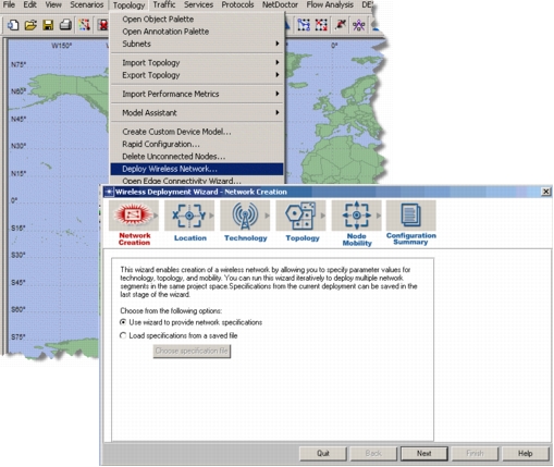
Choose Topology > Deploy Wireless Network…
Figure 20: Deploy Wireless Network
-
Select the network creation method from one of the given choices.
- Select “Use wizard to provide network specifications,” if you want to configure a new network segment with the help of the wizard, and click Next.
- Select “Load specifications from a saved file,” if you want to use a file that you saved from a previous run of the wizard, and click the “Choose Specification File” button. A file chooser appears. Select the file you want to use. Click Next to continue.
-
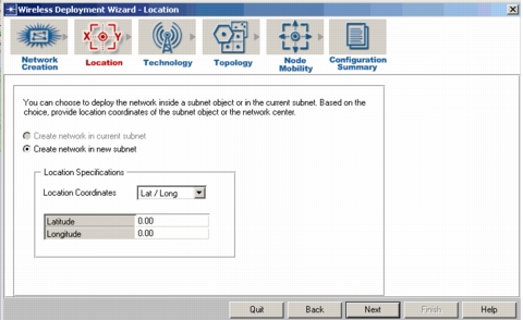
Specify the location in which you want to deploy your new network segment. Select from the given choices.
-
Select “Create network in current subnet,” if you have a subnet in your project that is defined in meters. Otherwise, this option is unavailable.
- Define Location Specifications in terms of X and Y coordinates, and click Next.
-
Select “Create network in new subnet,” if you want to deploy this network in a new subnet. If you have a current network not defined in units of meters, you must use this option.
- Define Location Specifications in terms of degrees, and click Next.
Figure 21: Define Location of Wireless Network
-
-
Deploy a technology.
5.1 Select the wireless technology you want to deploy in this network.
5.2 Define the parameters for the technology. Press Next.
Figure 22: Define Wireless Technology for Network Segment
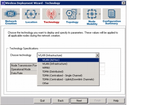
The parameters that appear in the table depend upon the technology you selected for deployment.
WLAN (Infrastructure)
- Node Transmission Power (W) – Provide the transmission power (in wattage) to use for each node
- Operational Mode – Specify 802.11a, 802.11b, or 802.11g.
- Data Rate – Choose data rate based on the Operational Mode selected
WLAN (Ad Hoc)
- Node Transmission Power (W) – Provide the transmission power (in wattage) to use for each node
- Operational Mode – Specify 802.11a, 802.11b, or 802.11g
- Data Rate – Choose data rate based on the Operational Mode selected
- Ad Hoc Routing Protocol – Choose the routing protocol that you want to deploy in this segment: AODV, OLSR, DSR, or GRP
WiMAX
- Subscriber Node Transmission Power (W) – Provide the transmission power (in wattage) to use for each subscriber node
- Base Station Transmission Power (W) – Provide the transmission power (in wattage) to use for each base station
- Pathloss and Multipath Model – Choose the Multipath Channel Model and the Pathloss Model to use for each subscriber node. This will also set the Shadow Fading Standard Deviation
TDMA (Distributed)
- Node Transmission Power (W) – Provide the transmission power (in wattage) to use for each mobile TDMA node.
- Primary Channel Set Base Frequency (MHz) – Provide the minimum frequency of the channel set (in MHz) used in automatic assignment of channels
- Primary Channel Bandwidth (MHz) – Provide the bandwidth of each channel
- MAC/PHY Configuration – Choose TDMA MAC/PHY configuration that will be used by the deployed TDMA networks
TDMA (Centralized - Single Channel)
- Node Transmission Power (W) – Provide the transmission power (in wattage) to use for each mobile and controller TDMA node
- Primary Channel Set Base Frequency (MHz) – Provide the minimum frequency of the channel set (in MHz) used in automatic assignment of channels
- Primary Channel Bandwidth (MHz) – Provide the bandwidth of each channel
- MAC/PHY Configuration – Choose TDMA MAC/PHY configuration that will be used by the deployed TDMA networks
Note: The same channel will be used for uplink and downlink transmissions.
TDMA (Centralized - Uplink/Downlink Channels)
- Node Transmission Power (W) – Provide the transmission power (in wattage) to use for each mobile and controller TDMA node
- Primary Channel Set Base Frequency (MHz) – Provide the minimum frequency of the channel set (in MHz) used in automatic assignment of uplink channels
- Primary Channel Bandwidth (MHz) – Provide the bandwidth of each uplink channel
- Secondary Channel Set Base Frequency (MHz) – Provide the minimum frequency of the channel set (in MHz) used in automatic assignment of downlink channels
- Secondary Channel Bandwidth (MHz) – Provide the bandwidth of each downlink channel
- MAC/PHY Configuration – Choose TDMA MAC/PHY configuration that will be used by the deployed TDMA networks
LTE
- UE Transmission Power (W) – Provide the transmission power (in wattage) to use for each UE
- eNodeB Transmission Power (W) – Provide the transmission power (in wattage) to use for each eNodeB
- PHY Profile – Provide the PHY profile that will be used by the deployed LTE network
- Pathloss Model – Choose the Pathloss Model to use for each UE. This will also set the Shadow Fading Standard Deviation.
Cell Size Based Transmission Power
For any technology, when the Transmission Power is set to "Cell Size Based," the transmission power will be auto-calculated with free-space pathloss formula based on the selected cell size and the transmission frequency of the selected technology such that the received power at the boundary of a cell will be -72 dB. The transmission power of a base station will be set to twice the transmission power of a subscriber node or a UE.
Other
- No parameters appear \ -
Specify a geographical overlay for your wireless subnet.
6.1 Select from the choices shown in the following figure in the “Choose Geographical Overlay” drop down menu.
The illustration in the dialog box shows an example of the currently selected overlay and node placement. Red dots indicate base stations, and gray dots indicate mobile nodesFigure 23: Define a Geographic Overlay for Wireless Network
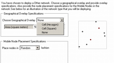
6.2 Configure the area for the network.
- None – Define the area in square meters.
- Cell (Hexagon) – Define the number of cells and the cell radius in kilometers.
- Cell (Square) – Define the number of cells and the length of the squares in kilometers.
6.3 Specify “Mobile Node Placement Specifications.” Values are Random, Grid, or Circular within each cell. If you select Grid, provide the number of rows and columns in the grid.
-
Specify the node models with which to populate the network segment. Choose the Node Model, Count (per cell), and Node Name Prefix for the node types that appear based on the technology you selected:
-
WiMAX – Specify parameters for Base Stations and Subscriber Stations
-
WLAN (Infrastructure) – Specify parameters for Access Points and Mobile Nodes
-
WLAN (Ad Hoc) – Specify parameters for Mobile Nodes
-
TDMA (Distributed) – Specify parameters for Mobile Nodes
-
TDMA (Centralized - Single Channel) – Specify parameters for Controller and Mobile Nodes
-
TDMA (Centralized - Uplink/Downlink Channels) – Specify parameters for Controller and Mobile Nodes
-
LTE – Specify parameters for eNodeB and UEs
For LTE, you can also specify with which EPC node the deployed UEs will be associated.
-
Other – Specify parameters for Gateways and Mobile Nodes
Note: The Node Name Prefix prepends a text string to a generated node name, assuring unique node names in this network segment.
7.1 Select the “Connect all {Base Stations | Gateways | Access Points} using a backbone network” checkbox if you want the nodes connected to a backbone IP cloud. Note that the access point or gateway must have a serial interface for connectivity to be established. If a backbone IP cloud is present from a previous deployment using the wizard, that IP cloud will be used in this deployment, as well. Click Next.
-
-
Specify Node Mobility parameters for the wireless network segment. Add or delete rows to apply multiple profiles.
8.1 Specify Trajectory Information. You can accept Random Waypoint (Auto Create) default or choose either a mobility profile that is defined on the mobility node or apply a trajectory file that exists in your mod_dirs from the drop down list.
Figure 24: Specify Trajectory Information
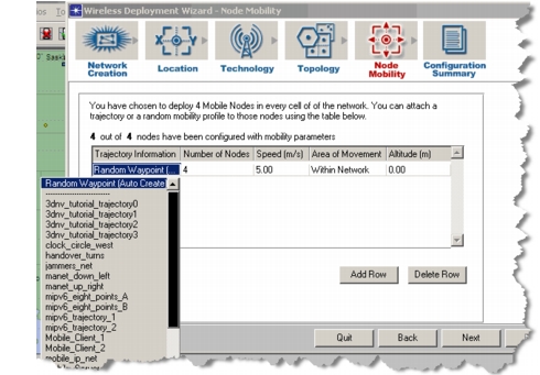
8.2 Select the number of nodes (up to the total number already specified for this network) to which to apply the trajectory information.
8.3 Select the movement speed of the nodes, in meters per second.
8.4 Specify the Area of Movement, within the cell or within the network (all cells). Note, this option is available when you choose a mobility model but not when you choose a trajectory file.
8.5 Specify the Altitude of the nodes. Note, this option is available when you choose a mobility model or a relative trajectory but not when you choose an absolute trajectory.
8.6 Click Next when finished.
-
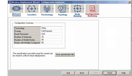
Review the Configuration Summary showing the specifications you entered.
9.1 To save these specifications for later use, click on the “Save specification file” button. Specify a file name when the file chooser appears.
9.2 Click the Finish button when done.
Figure 25: Configuration Summary for Wireless Network Deployment