EPS Mobility Management (EMM)
Mobility management functions track the location and activity of a UE in the network. The following topics are contained in this section:
- EMM UE State Management
- EMM Attach Procedure Support
- Initial Cell Search and Selection
- Attributes Affecting Cell Selection
- Attributes Affecting UE Transition to Idle Mode
- UE Transition from Idle Mode
- Cell Monitoring and Reselection Process from Idle Mode
- Tracking Area Updates
- Handover
- Radio Link Monitoring and Failure
EMM UE State Management
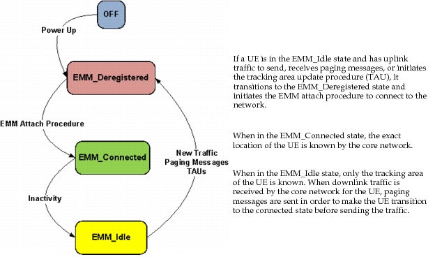
As a UE participates in an LTE network, it may change EMM states (see Figure 323) in order to conserve energy. The core network needs to know the location of a UE for traffic transmission, but if the UE is in the idle state, the core network only knows a general location (tracking area) for the UE.
EMM UE States
As shown in the following figure, the UE can be in one of three states. These states are discussed below.
Figure 323: EMM UE States
-
EMM_Deregistered – A UE is in this state when it is waiting to finish the EMM Attachment procedure with the EPC.
-
EMM_Connected – A UE enters the EMM_Connected state when the registration and attach process is complete. While in this state, the exact location of the UE is known to the core network.
Note: A UE in the EMM_Connected state can achieve power savings by using DRX in RRC_Connected mode. For more information, see Discontinuous Reception (DRX) in Connected Mode.
-
EMM_Idle – When the UE enters the EMM_Idle state, it can achieve significant power savings; however, the location of the UE is only known by the granularity of the tracking area.
Note: To learn more about how a UE transitions to the idle state, see Tracking Area Updates.
EMM Attach Procedure Support
Registration of UEs to the LTE network via the EMM Attach procedure is modeled, and is implemented based on Figure 5.3.2.1-1: "Attach Procedure" in 3GPP TS 23.401 "General Packet Radio Service (GPRS) enhancements for Evolved Universal Terrestrial Radio Access Network (E-UTRAN) access".
The model supports connecting an eNodeB to multiple EPCs. In such topologies, the selection of an EPC for a UE is via the configuration of the "Serving EPC ID" attribute on that UE.
Note: A diagram of the various states supported for a UE is shown in Figure 323.
Initial Cell Search and Selection
Cell search and selection procedures are performed during initial attachment.
PLMN Selection
In the LTE model, the UE is configured with a single home public land mobile network (HPLMN).
- The HPLMN identifier is the LTE > Serving EPC ID attribute
- Cell search is only performed for the configured HPLMN
- If suitable cells are not found for the HPLMN, then the UE continues to search for a suitable cell
Cell Search and Synchronization
Once an EPC has been selected, the UE performs a cell search by scanning the DL frequencies of all eNodeBs that serve this EPC to determine a suitable eNodeB.
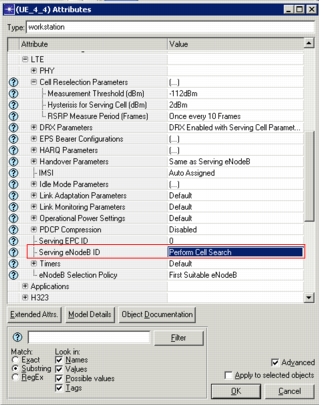
Note: When an explicit eNodeB is specified in LTE > Serving eNodeB ID on the UE, rather than the value "Perform Cell Search", the cell search begins with that carrier frequency.
- Cell Synchronization – In each carrier frequency, the UE attempts to synchronize with the cells. The model supports explicit transmission of Primary Synchronization Signal (PSS), Secondary Synchronization Signal (SSS), Master Information Block (MIB), and System Information Block (SIB). During cell search, the UE will synchronize with the strongest cell in each carrier frequency.
- Cell Measurement – The UE supports the measurement of RSRP for each cell to aid in the cell selection process. Reference Symbols are not supported. Instead RSRP is measured for the MIB packets.
- Cell Selection – Once a UE has chosen a candidate cell, that is, the strongest cell, for a carrier frequency, it evaluates the cell selection criteria.
- Cell Selection Threshold – LTE > eNodeB Selection Threshold (configured on the eNodeB) specifies the minimum signal power for a UE to join the eNodeB.
- Cell Selection Criteria – The following criteria is evaluated for a cell to be selected as the serving cell:

Table 148: Cell Selection Criteria
| Value | Description |
|---|---|
| Q_rxlevmeasured | Measured cell RX level value (RSRP) |
| Q_rxlevmin¹ | Minimum required RX level in the cell (dBm) |
Note 1: Mapped to Cell Selection Threshold on the eNodeB
Note: The cell should belong to the HPLMN of the UE. Cell-barring and TAC conditions are not supported.
- Attach Procedure – Once the UE-AS has selected the cell, it conveys this information to the NAS to initiate the network attach procedure.
- Cell Selection Failure – If a suitable cell is not found for the HPLMN, the UE continues cell search and selection indefinitely.
Attributes Affecting Cell Selection
EPCs Served
Configured on the eNodeB. Specifies the list of PLMNs (EPCs) that this eNodeB can service. If set to "All" (default), then this eNodeB can service all PLMNs (EPCs) in the network. When "All" PLMNs are supported by an eNodeB, the UE considers this eNodeB as a valid eNodeB for cell selection.
eNodeB Selection Threshold
Configured on the eNodeB. Specifies the minimum RSRP threshold for a UE to select this eNodeB.
eNodeB Selection Policy
Configured on the UE. This attribute specifies the eNodeB selection policy during cell search.
- First Suitable eNodeB: Results in the UE selecting the first eNodeB that matches the cell selection criteria
- Best Suitable eNodeB: Results in the UE selecting the best eNodeB from eNodeBs meeting cell selection criteria in all frequencies belonging to this PLMN.
Serving EPC ID
Configured on the UE. Specifies to which EPC node this UE will be connected. (See also EPCs Served).
Serving eNodeB
Configured on the UE. Specifies the eNodeB selection method. The use of this attribute depends on the efficiency mode setting (see Efficiency Mode).
Figure 324: Serving eNodeB Attribute
- Efficiency Enabled – In this mode, the following behavior applies.
- When an explicit eNodeB is specified, and the eNodeB services the EPC configured on the UE, the UE selects this eNodeB irrespective of distance or power.
- If the eNodeB does not service the EPC, then the UE defaults to "Perform Cell Search", in which case the UE selects the best eNodeB (based on distance) from the eNodeBs that service the EPC configured on the UE.
- Physical Layer Enabled – In this mode, the following behavior applies.
- When an explicit eNodeB is specified, and the eNodeB services the EPC configured on the UE, the UE searches the frequency of the specified eNodeB first. The eNodeB is selected if it meets "Cell Selection Criteria", even if it is not the best eNodeB.
- If the specified eNodeB does not service the EPC, does not meet the cell selection criteria, or is not discovered, the UE will default to "Perform Cell Search".
Attributes Affecting UE Transition to Idle Mode
When the attach procedure is completed, the UE enters into the connected state. An inactive UE in connected state may transition to the idle mode based on the settings of the following attributes within LTE > Idle Mode Parameters.
Note: The term "idle mode" is used throughout this section to refer to the EMM_Idle state.
- Idle Mode Support – Specifies if the UE supports the idle mode. Values are Enabled, Disabled, or eNodeB Triggered (meaning that the eNodeB tells the UE when to enter the idle mode). If this attribute is set to "eNodeB Triggered", the UE transitions to the idle mode based on the setting of a timer on the eNodeB. See RRC Connection Release Timer (on eNodeB) for more information
- Timers
- T3440 – Specifies the length of an inactivity period, after which the UE enters the idle state. If the Idle Mode Support value is set to "eNodeB Triggered," this timer is ignored and the setting of the RRC Connection Release Timer on the eNodeB is used instead.
RRC Connection Release Timer (on eNodeB)
Specifies the length of inactivity (in seconds) after which a UE will be placed into the idle mode by initiating the procedure of releasing that UE's RRC connection, if Idle Mode Support on the UE is set to "eNodeB Triggered" or "Enabled". The value for this timer is generally set for a shorter period of time than the T3440 timer on the UE, making this the preferred timer for use in placing UEs into the idle state.
UE Transition from Idle Mode
A UE will leave the idle mode and re-initiate the attachment procedure in case of any of the following events:
- Uplink Traffic. When the UE has traffic to send, it reattaches to the core network. No paging traffic is required.
- Tracking Area Update. If the UE moves into a different tracking area, or the T3412 timer expires (explained below), the UE will leave the idle mode and will send a TAU to the EPC with its current tracking area. For more information, see Tracking Area Updates.
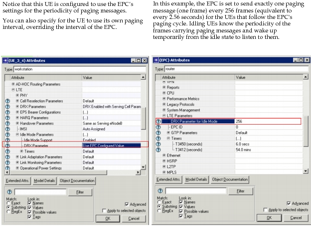
- Paging. The eNodeB sends broadcast paging messages on a known frame when it has traffic for a UE that is in the idle mode. At the designated interval, the UE listens for the paging messages, whether or not there is traffic for it. The UE leaves the idle mode to receive the traffic when it sees its identification included in the paging message. The following parameter specifies the duration of the paging cycle.
- DRX Parameter – Specifies (in frames) the length of the paging cycle, after which the UE wakes up to listen for broadcast paging messages. The default value is 256 frames, which is equivalent to 2.56 seconds. This is the "worst case" length of time for the UE to wake up and sense paging messages. You can specify a value on the UE or choose "Use EPC Configured Value" to let the EPC set the length of the paging cycle. See RRC Connection Release Timer (on eNodeB) for a comparison of the settings on the UE and on the EPC.
Figure 325: EMM Paging Cycle
Note: Although the idle mode can result in significant power savings for the UE, the need for the UE to reattach upon leaving the idle mode results in more signaling traffic in the backbone network.
Cell Monitoring and Reselection Process from Idle Mode
While a UE is in the idle mode, it monitors the signal strength of the cell on which it is camped so that when the UE needs to leave the idle mode, it knows which cell to select. Ordinarily, the UE would use the handover procedure to select a new cell, but the process differs for a UE in the idle mode. The following parameters under LTE > Cell Reselection Parameters control the cell monitoring and reselection process.
Note: A UE in the idle mode continually assesses cells but does not select a cell until it needs to wake up from the idle mode.
-
RSRP Measure Period – Controls how often, in frames, a UE that is in the idle state measures the RSRP of the cell it is camped on. The default value is 10, meaning that every tenth frame, the UE will check the RSRP of the cell on which it is camping.
-
Measurement Threshold – Specifies the low RSRP threshold (in dBm) that determines if a UE in idle mode should begin to search for a new cell on which to camp. This threshold is only used in the idle mode; if the UE is in the RRC_Connected state, attributes under Handover Parameters will be used.
-
Hysteresis for Serving Cell – In conjunction with the Measurement Threshold attribute (shown above), this attribute helps to determine whether a cell will be selected as a potential serving cell by a UE in idle mode. The RSRP of the new cell should be greater than the RSRP of the current cell by at least this value for the cell reselection to proceed.
For example, if this attribute is set to 2 dBm, and the Measurement Threshold attribute is set to -112 dBm, assuming the RSRP measured in the current cell is just below the threshold, then a cell must have a signal of at least -110 dBm to be selected (-112 + 2 dBm = -110 dBm)
Tracking Area Updates
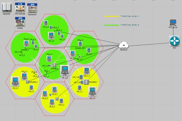
The location of an idling UE is known by the core network at the granularity of a tracking area. A tracking area is a collection of eNodeBs and their sectors and can represent a logical or geographic subset of the LTE network (for example, Boston or Region 3). UEs may remain within a tracking area or move into other tracking areas over time. Periodically, or when it changes tracking areas, a UE in idle mode sends tracking area update (TAU) messages to the core network.
The UE setting in LTE > Idle Mode Parameters > Timers > T3430 specifies the maximum allowable time between the transmission of the tracking update from the UE and the receipt of an accept message from the core network. If the timer expires without the receipt of an accept message, the UE begins the tracking area update process again.
The following figure, taken from the "idle_mode_study" scenario of the LTE example project, shows two tracking areas: one highlighted in yellow and the other in green. Tracking areas are specified in the LTE > Tracking Area ID attribute of the eNodeB.
Figure 326: LTE Tracking Areas
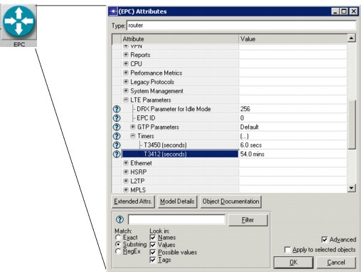
The periodicity of the TAUs is determined by the T3412 timer on the EPC. This can be set to a period from 6 minutes to 196 minutes, as specified in section 10.2 of 3GPP TS 24.301. The timer is restarted when a TAU is sent in case of the UE moving into a new tracking area as a result of the cell reselection procedure.
Figure 327: T3412 Timer
Handover
LTE handovers allow for smooth transitions from one cell to the next as the mobile node moves through the network. The most common driver for a handover is deteriorating signal quality.
Handover (mobility management in the Connected state) is initiated and controlled by the eNodeB, with assistance from the UE. The modeling of LTE handovers is supported, as follows.
-
Handover Capabilities – The model supports all handover procedures described in the LTE standard. Specifically, we support the following capabilities, including a standards-based implementation of all control messages, and of UE, eNodeB, and EPC procedures.
-
Intra- and inter-frequency handover is supported
-
Handover between cells using FDD and TDD is supported
If the handover type is set to Intra-frequency, you must select the same center frequency for the Downlink FDD channel and the TDD channel. For more information on setting frequencies, see FDD/TDD Parameters.
If the above requirement is not satisfied, the handover type must be set to Inter-frequency.
-
Handover between cells using S1 interface is supported
-
Handover between cells using the X2 interface is supported
-
Handover data forwarding is supported and configurable on the individual bearers
-
-
UE Measurement and Reporting – The model supports Layer-3 (AS) measurement of RSRP and RSRQ based on physical layer RSRP and RSRQ measurements. Every 200ms, the UE obtains the latest measurements from the physical layer and updates its Layer-3 measurement module. The Layer-3 measurement module filter coefficients can be configured via attributes.
The model supports inter-frequency measurements using "measurement gaps".
- If inter-frequency handover is enabled, the serving eNodeB will periodically stop all transmissions to the UE. Simultaneously, the UE will stop all its current actions and will scan the list of carrier frequencies to measure detected eNodeBs. Upon completion of the measurement gap, the UE returns to normal operation.
The model supports all the measurement reporting techniques described in the standard (periodic, Event A1-A5).
- Periodic reporting is based on report_interval and number of reports
- Event triggered reports (A1-A5) use RSRP and/or RSRQ thresholds and hysteresis values to determine if a report should be generated and what contents should be in the report. The report_interval and num_reports attributes govern the number of reports sent to the eNodeB.
- The transmission/reception of measurement configuration information is explicitly modeled. UE measurement and reporting configuration can be specified via attributes.
-
Handover Decisions – The Serving eNodeB receives reports from the UE either due to periodic reporting or event-triggered reporting. When the reported measurements violate the handover triggers, the serving eNodeB decides to handover the UE to a different cell. The serving eNodeB selects a set of potential target eNodeBs and initiates handover.
Support in Riverbed Modeler is as follows:
-
Handover Triggers – Handover at the serving eNodeB can be triggered either due to RSRP threshold violation and/or RSRQ threshold violation.
Handover trigger thresholds are user-configurable.
-
Target eNodeB Selection – Once a handover trigger is violated, the serving eNodeB selects a list of potential target eNodeBs based on the measurements reported by the UE.
- The serving eNodeB ranks the neighbor eNodeBs based on the RSRP and RSRQ measurements reported by the UE. The RSRP and RSRQ ranking weights are configurable via attributes.
- Only eNodeBs in the same PLMN are considered for selection
-
Cell Selection – The cell selection operation is invariant to FDD or TDD technology, since subframes 0 and 5 are always downlink for all TDD frame types (see Figure 317).
-
-
Handover Procedure – Once a target eNodeB is selected, the serving eNodeB initiates the handover procedures as defined in the standard.
In the handover preparation phase, if an X2 interface is available, then an X2 handover is initiated. Otherwise, an S1 handover is initiated.
The target eNodeB accepts the UE if at least one non-GBR bearer is accepted.
Upon successful completion of the handover preparation phase, the serving eNodeB initiates the handover execution phase by sending the Handover command message to the UE. The serving eNodeB also initiates status transfer and data forwarding to the target eNodeB. Note that data forwarding is configurable on a per-bearer basis.
- Downlink data forwarding is supported for RLC UM-based bearers
- Uplink and downlink data forwarding is supported for RLC AM-based bearers
- Direct data forwarding using X2 and indirect data forwarding using S1 are supported
- When the UE joins the target eNodeB, the target eNodeB starts the Handover Completion phase, wherein all data bearers are established with the EPC. The UE context is also released at the original serving eNodeB.
-
Handover Failure – During handover, the procedure may fail. The following failure scenarios and remedial action are supported:
-
Target eNodeB Responds with Handover_Failure – Admission control at the target eNodeB cannot accept this UE.
The serving eNodeB selects another target eNodeB and proceeds with the handover. If all potential target eNodeBs are exhausted, then the handover procedure is terminated. In this case, the UE may eventually perform radio link failure and re-attach to another eNodeB.
-
Incomplete Handover – UE loses coverage with serving eNodeB before receiving the Handover_Command message.
The UE will detect the radio link failure and recovery procedure. If the selected cell is a "prepared" cell, then the RRC Connection Re-establishment procedure will succeed, and the UE is successfully handed over to the new eNodeB.
If the selected cell is not a "prepared" eNodeB, then the Connection Re-establishment procedure will fail, and the UE will detach and perform the initial cell selection procedure. If the selected cell is the serving cell, then handover is cancelled, and the eNodeB continues to serve the UE.
-
-
Handover Cancel – The handover procedure is protected by timers. If handover fails due to loss of control messages, then upon timer expiry, the Handover Cancel procedure will be executed.
Radio Link Monitoring and Failure
The model supports radio link failure detection and recovery based on the procedures in 3GPP TS 36.331.
The UE continuously monitors the downlink signal quality of the serving cell and detects radio link failure based on link monitoring and other triggers.
-
Radio Link Monitoring – The physical layer of the UE continuously monitors the signal quality (RSRQ) of the serving cell. The physical layer sends an out-of-sync indication to the AS process if the measured RSRQ is lower than Qout. An in-sync indication is sent if the measured RSRQ is greater than the Qin threshold [Section 7.6 in 3GPP TS 36.133].
The model supports detection of radio link problems upon receiving N310 continuous out-of-sync indications and recovery from radio layer problem upon receiving N311 continuous in-sync indications.
Qin, Qout, N310, and N311 are configurable attributes.
-
Radio Link Failure Triggers – The model supports all of the radio link failure detection triggers specified in the standard [Section 5.3 in 3GPP TS 36.331].
- Detection of radio link failure upon expiry of T310
- Detection of radio link failure upon RACH failure
- Detection of radio link failure upon retransmission threshold reached indication from RLC AM
-
Radio Link Recovery – The model supports the RRC Connection Re-establishment procedure as specified in Section 5.3.7 in 3GPP TS 36.331.
Upon detection radio link failure, a UE will reset MAC and PHY parameters, and then perform cell search and selection to determine a suitable cell.
Once a cell has been selected, the UE will perform the Connection Re-establishment procedure. If the procedure is successful, the UE continues with normal operation.
-
Radio Link Recovery Failure – After a radio link failure detection—due to either a suitable cell not found during cell selection or the failure of the RRC Connection Re-establishment procedure—the UE moves to the RRC Idle state.
The model does not support Idle mode procedures, therefore the UE will detach from the network upon entering the RRC Idle state.
The NAS layer then performs the PLMN selection and initial cell search and selection procedures.