How Antenna Patterns Are Represented in the Antenna Pattern Editor
An antenna pattern model represents the three-dimensional gain of an antenna by specifying the gain at regular intervals of the 3D pattern. To determine these intervals, the pattern is decomposed into a set of horizontal slices called polar planes. Within each polar plane, the antenna’s gain is specified at regular angular intervals (azimuth values). By default, an antenna pattern model defines 36 polar planes and 72 azimuth values per plane. (To change these numbers, see Specifying the Resolution of an Antenna Pattern.) A tabular representation of the antenna pattern can be seen in the Gain Table.
Note: The coordinate system used to represent an antenna pattern differs from the geocentric and body coordinate systems, as shown in Figure 38 “Polar, Azimuth Coordinate System Used to Represent Antenna Patterns” on page 59. Be careful not to confuse pattern angles with pointing angles.
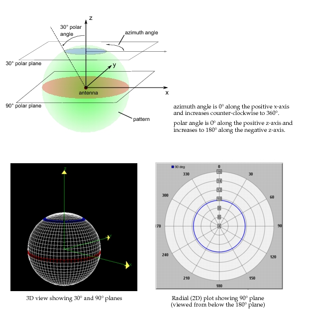
The following figure shows a spherical antenna pattern with a slice taken at the 30° polar plane. Also shown in this figure are the 90° polar plane; the x, y, and z axes (used for reference only); and the Antenna Pattern Editor’s 3D View of the pattern.
Figure 72: Antenna Pattern Representation
Antenna pattern models define two reference directions—boresight and rotation handle—that are used to orient the pattern in three-dimensional space. You can set the reference directions for an antenna pattern as described in Specifying the Boresight and Rotation Handle of an Antenna Pattern.