3D View
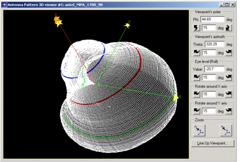
This view of an antenna pattern shows a 3-dimensional representation of the pattern, in which the surface of the shape shows the normalized gain in all directions. The x, y, and z axes are shown, as is the boresight and the rotation handle (if any). Individual polar planes in the pattern are colored to match the planes displayed in the polar plot (if one is open) or the rectangular plot.
You can open any number of 3D viewers, allowing simultaneous views of the pattern from different viewpoints.
Figure 81: 3D View
To display a 3D view:
Procedure 38: Displaying a 3D View
-
Choose Antenna > Display New 3D Pattern Viewer, or click the Display New 3D Pattern Viewer toolbar button.
A 3D viewer opens in a new window.
-
Use the viewpoint controls to rotate the pattern, zoom the view, or adjust the viewpoint.
- You can set the viewpoint directly by entering view angles in the polar, azimuth, and eye level fields (labeled Phi, Theta, and Value).
- You can change the step size for the rotation buttons (default: 15 degrees) by entering a new step size in the corresponding fields.