Defining an Antenna Pattern Numerically
You can define an antenna pattern by entering its gain values in the gain table of the Antenna Pattern Editor. This view is displayed when the Polar/Azimuth Gain Table tab is selected (see Gain Table for details). In the gain table, you enter one gain value for each combination of polar and azimuth angles. Alternatively, you can create the gain table in an external tool and import it, as described in Exporting and Importing an Antenna Pattern Gain Table.
Procedure 31: Editing the Antenna Pattern Gain Table
Note: If the pattern is specified by an external library, you cannot edit the gain table.
-
Click the Polar/Azimuth Gain Table tab in the Antenna Pattern Editor.
-
Make sure the “Defined manually using gain table” checkbox is selected.
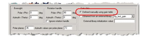
-
Individually edit the gain value in each cell.
If desired, you can open a Polar (Radial) Plot or 3D View to watch what effect your changes have on the antenna pattern.
-
Choose File > Save or File > Save As… to save the antenna pattern model.
Exporting and Importing an Antenna Pattern Gain Table
The data in a gain table can be exported to and imported from a tab-separated ASCII file. This lets you use a text editor or spreadsheet to create, modify, or examine the data.
To export and import gain table data, use these menu operations:
- Antenna > Export Gain Table to ASCII File…
- Antenna > Import Gain Table from ASCII File…
The text file format is:
Polar planes   <number>
Azimuth values   <number>
Polar\Azimuth   <1st azimuth value>   <2nd azimuth value> …
<1st polar value>   gain   gain …
<2nd polar value>   gain   gain …
The values in each line must be separated by single tabs.
Note: The azimuth values (line 3) and polar values (first entry in gain lines) are included for human readability. They are not used by the import process; instead, the Antenna Pattern Editor computes these values based on the specified number of polar and azimuth planes.