Wireless Objects in the Node Domain
This section provides an overview of the node objects included in the Wireless functionality. These objects are radio transmitters, receivers, and antennas. Detailed information about these objects and their attributes appears in “Node Domain” on page 145.
Table 6: Node Model Objects
| Object Type | Definition | Icon |
|---|---|---|
| Radio transmitter | Allows packets to be sent outside of the node’s boundary via radio links. |  |
| Radio receiver | Allows packets to be received from other nodes via radio links. |  |
| Antenna | Optionally can be used to exchange packets with other nodes, when antenna directionality or gain need to be modeled. |  |
The following considerations apply to wireless objects in node models.
- Radio transmitter and receiver modules do not support logical associations.
- Wireless modules support packet stream connections as described in the following table.
Table 7: Support for Packet Stream Connections by Module Type
| Module Type | Source or Destination | # of input streams | # of output streams |
|---|---|---|---|
| Antenna | Both | User-defined (from radio transmitter) | User-defined (to radio receiver) |
| Radio Receiver | Both | 1 (from antenna) | User-defined |
| Radio Transmitter | Both | User-defined | 1 (to antenna) |
Transmitter Module
Unlike other transmitter modules, radio transmitter modules can have a single output packet stream, for connection to an antenna module. Radio transmitters do not connect to radio link objects, because there are none. Instead, the Simulation Kernel determines which radio receiver modules are capable of receiving each packet transmitted by a radio transmitter module, based on the attributes of those modules. Because there is no radio link object, transmission-related properties are specified as attributes of a radio transmitter module.
For more information, see:
Receiver Module
Unlike point-to-point and bus receiver modules, radio receiver modules can have a single input packet stream, for connection to an antenna module. There are no corresponding radio link objects. Instead, the Simulation Kernel determines which radio receiver modules are capable of receiving each packet transmitted by a radio transmitter module, based on the attributes of those modules. Because there is no corresponding radio link object, reception-related properties are specified as attributes of a radio receiver module. For more information, see the description of radio receiver modules in “Radio Receiver Object” on page 158 and the description of the radio transceiver pipeline in Chapter 10 “Radio Transceiver Pipeline” on page 263.
Radio receiver channel objects respond to the flush command, which causes them to flush all packets currently being received. The op_ima_obj_command() Kernel Procedure is used for this purpose. For more information, see the description of this procedure in Chapter 10 “Internal Model Access” on page 1.
Antenna Module
Antenna modules specify the antenna properties for radio transmitter or receiver modules. The fact that these properties are specified externally to the transmitter or receiver modules makes it convenient to specify the same set of properties for multiple transmitters or receivers within a node. This corresponds, for example, to the common real-world case in which a transmitter and receiver share a common antenna. Radio transmitter and receiver modules that are not connected to an antenna module behave as though they are connected to an antenna with 0dB gain in all directions.
Antennas are associated with radio transmitter and receiver modules by means of packet streams. An antenna module can accept the output streams of one or more radio transmitter modules and produce input streams for one or more radio receiver modules. A single antenna module, therefore, might have multiple input and output stream connections, as shown in the following figure. However, connections to modules other than radio transmitters and receivers are not permitted.
Figure 34: Sharing an Antenna Module
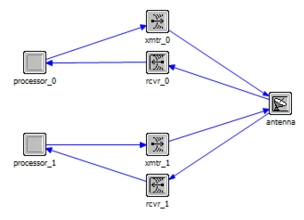
The significance of antenna modules within a simulation is their effect on radio transmission and reception, as governed by the antenna’s directional gain pattern and its orientation in space. For details, see
Antenna Location
The location of an antenna in three-dimensional space is determined by where the antenna is physically located on the node carrying it, as well as by the location of the node itself. Modeler models the location of an antenna on a node with the “antenna location” attribute of the antenna module. This compound attribute has sub-attributes for the x, y, and z coordinates of the antenna. These coordinates are given in meters relative to the center of the node that contains the antenna module. (The body coordinate system used for this is discussed in Body Coordinates.)
You can specify antenna location from the GUI in either of two ways:
- Graphically, in the Physical Layout View of the Node Editor
- Numerically, by editing the sub-attribute values
In addition, you can modify the value of the antenna location attribute during a simulation. This might be necessary if the antenna moves relative to the node carrying it (for example, an antenna mounted on a telescopic mast of a vehicle). See Accessing Antenna Module Attributes from Code for details.
Antenna Pointing
When you point an antenna, you are orienting its antenna pattern in three-dimensional space such that a defined part of the pattern is directed at a specific target. The antenna pattern is treated as a rigid object, so that orienting a particular part of the pattern in a given direction affects the gain for all other directions as well. In Modeler, antenna pointing is modeled by setting the values of attributes on the antenna module. (See Antenna Pointing Attributes for descriptions of these attributes.)
The primary target of an antenna typically corresponds to the position of a node that is intended to receive a transmission (or from which a transmission is expected). The antenna boresight is pointed at the primary target.
The secondary target of an antenna provides a reference for rotating the antenna pattern around the boresight. This lets you position the sidelobes of patterns that are not symmetric around the boresight.
When pointing an antenna, Modeler performs these steps:
- Align the antenna pattern boresight with the vector connecting the antenna to the primary target.
- Rotate the pattern around the boresight until the semi-plane formed by the boresight and rotation handle contains the secondary target.
Figure 35: Antenna Pointing
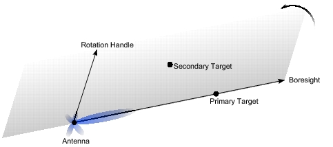
You can modify the value of target location attributes during a simulation to change the direction in which the antenna is pointed. This technique is useful if you want an antenna to track a mobile target. (Note: You should change both the primary and secondary targets to avoid having the pattern rotate around the boresight as the antenna moves.) See Accessing Antenna Module Attributes from Code for details.
Antenna Pointing Attributes
The antenna module attributes used to point the antenna are listed in Table 8 and discussed in the following paragraphs.
Antenna modules specify one or two targets that are used to point the antenna by defining the orientation of the antenna pattern. Antenna targets can be defined in either of two coordinate systems (described in Antenna Coordinate Systems):
- Body coordinates – used to specify a point relative to the node containing the antenna. In physical terms, this models an antenna that is “bolted” to an object and always points in the same direction relative to that object’s heading.
- Global coordinates – used to specify a point in space, such as a receiving node. In physical terms, this models an antenna that is free to move and automatically follows the specified target, regardless of the parent object’s heading.
Table 8: Antenna Pointing Attributes
| Attribute | Description |
|---|---|
| target location coordinate type | Specifies whether the primary target location is given in global or body coordinates. |
| target location: global coordinates target latitude (deg) target longitude (deg) target altitude (m) |
Compound attribute specifying a point in space at which the antenna boresight is pointed. Only meaningful when “target location coordinate type” is set to “global”. |
| target location: body coordinates x (m) y (m) z (m) |
Compound attribute specifying a point in space at which the antenna boresight is pointed. Only meaningful when “target location coordinate type” is set to “body”. |
| secondary target location coordinate type | Specifies whether the secondary target location is given in global or body coordinates. |
| secondary target location: global coordinates target latitude (deg) target longitude (deg) target altitude (m) |
Compound attribute specifying a point in space for antenna pattern rotation. Only meaningful when “secondary target location coordinate type” is set to “global”. |
| secondary target location: body coordinates x (m) y (m) z (m) |
Compound attribute specifying a point in space for antenna pattern rotation. Only meaningful when “secondary target location coordinate type” is set to “body”. |
| boresight polar (deg) boresight azimuth (deg) |
Specify a point on the antenna pattern that is pointed at the primary target.¹ |
Note 1: These attributes are included on the antenna module to allow use of antenna patterns developed prior to release 15.0. These older patterns do not include boresight information. For current antenna patterns, these attributes usually inherit values from the pattern.
The “target location coordinate type” and “secondary target location coordinate type” attributes specify which coordinate system is used for each target. For example, if “target location coordinate type” is set to “body”, the primary target location is given by the “target location: body coordinates” attribute and the “target location: global coordinates” attribute is ignored. You can use the same coordinate system for both targets of an antenna or mix them.
Every antenna module must specify a primary target location (using “target location coordinate type” and either “target location: body coordinates” or “target location: global coordinates”). This points the antenna pattern boresight. A secondary target location is needed only if the antenna pattern defines a rotation handle.
The “boresight polar” and “boresight azimuth” attributes define the boresight reference direction of the antenna. Usually this direction is inherited from the antenna pattern. However, patterns created prior to release 15.0 did not include reference directions, so you can use these attributes to specify the boresight when needed. (The polar and azimuth angles used by these attributes are described in “How Antenna Patterns Are Represented in the Antenna Pattern Editor” on page 232).
Antenna Pattern
Antenna patterns consist of a set of gain values that vary as a function of direction in three dimensions. Thus, a transmitter’s antenna provides a gain value with respect to every other point in space. The same is true of a receiver’s antenna. For a given transmission, the gains of both the transmitter and receiver antennas, with respect to each other, are typically taken into account.
Physically, an antenna pattern can be thought of as a three-dimensional object whose shape indicates the relative magnitudes of gain in each direction. The simplest case is a sphere, which represents an antenna pattern known as isotropic. An isotropic pattern radiates (or captures) power equally in all directions. Its gain is equal to 0 dB in all directions.
Figure 36: Isotropic Antenna Pattern
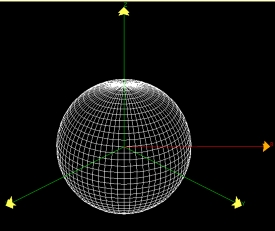
Other patterns can be thought of as deformations of the sphere that represents an isotropic pattern, with areas stretching further from the center corresponding to directions of higher gain. Regions of the pattern that are relative maxima of the gain function are called lobes. Likewise, other areas can be compressed toward the center of the sphere, indicating a gain less than unity. Where the gain reaches a relative minimum, the antenna pattern is said to have a null.
Figure 37: Antenna Pattern with Lobes
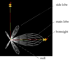
An antenna pattern is modeled separately from the antenna module and is associated with an antenna module by specifying its name as the value of the module’s “pattern” attribute. You can create antenna patterns with the Antenna Pattern Editor (described in Chapter 8 “Antenna Pattern Editor” on page 231) or by a program that uses the External Model Access (Ema) package.
Because an antenna pattern maps gain to all directions in a three-dimensional space, it can be represented as a function of two angle variables called polar and azimuth. As shown in the following figure, polar varies from 0 to 180 degrees and azimuth varies from 0 to 360 degrees. Together, they uniquely specify all directions in terms of vectors departing from the center of the pattern.
Figure 38: Polar, Azimuth Coordinate System Used to Represent Antenna Patterns
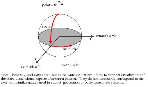
Note: Outside Modeler, the polar and azimuth angles are frequently referred to as phi (  ) and theta (
 ). However, the usage is not consistent. In mathematics, the azimuth angle is called theta and the polar angle is called phi. In physics and the electromagnetic world, this usage is reversed (azimuth is phi and polar is theta). You can choose how Modeler uses the terms theta and phi with the “antenna.spherical_model” preference.
An antenna pattern defines one or two reference directions that are used to orient the pattern in three-dimensional space (as described in Antenna Pointing). These directions are the boresight and the rotation handle. Typically, the boresight is defined as the direction of maximum gain (usually the center of the antenna’s main lobe). The rotation handle is an arbitrary direction (possibly a prominent side lobe) used to specify rotation of the pattern around the boresight. The rotation handle is needed only for patterns that are not symmetric around the boresight and thus is optional.
Antenna Coordinate Systems
Two coordinate systems are used when configuring antenna modules: body and global.
Global Coordinates
Global coordinates are used for pointing antennas at a target whose location is independent of the node containing the antenna. This coordinate system expresses locations in latitude, longitude, and altitude. For a discussion of global coordinates as used in Modeler, see “Global Coordinate System” on page 309.
Body Coordinates
Body coordinates are used for positioning antenna modules on a node and for pointing “bolted” antennas at a target. This coordinate system expresses locations as an x,y,z offset (in meters) from the center of the node containing the antenna. The following figure shows how the body coordinate system maps to a node.
Figure 39: Body Coordinate System
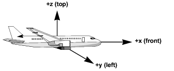
The directions on a mobile node (front, left, etc.) are determined by the node’s pitch, roll, and yaw attributes.
- If a trajectory is assigned to the node, the front of the node faces in the direction of travel (yaw) at any given time.
- If there is no trajectory, the front of the node is offset from north by the value of yaw.
For fixed nodes, the “front” of the node is assumed to face east (yaw = 90) and the “top” is straight up.
Accessing Antenna Module Attributes from Code
Using the op_ima_obj_attr_set_dbl() KP, you can modify the value of antenna attributes during a simulation. This lets you change the location or pointing direction of an antenna as the simulation progresses. For example, to track a target with an antenna, you could use code similar to this:
/* Get current location of target object. */
op_ima_obj_pos_get (target_objid, lat_ptr, long_ptr, alt_ptr, x_ptr, y_ptr, z_ptr);

/* Move the antenna target to track the target object. */
op_ima_obj_attr_set_dbl (ant_objid, “target latitude”, *lat_ptr);
op_ima_obj_attr_set_dbl (ant_objid, “target longitude”, *long_ptr);
op_ima_obj_attr_set_dbl (ant_objid, “target altitude”, *alt_ptr);
When accessed from code, the compound antenna attributes used in the GUI have different names and are treated as top-level attributes. For example, the “target latitude (deg)” subattribute of the “target location: global coordinates” compound attribute is accessed in code as “target latitude” (as in the preceding code sample). The following table shows corresponding attribute names for the GUI and code.
Table 9: Antenna Attribute Names in GUI and Code
| Compound Attribute Name in GUI | Attribute Name in Code |
|---|---|
| antenna location x (m) y (m) z (m) |
antenna x antenna y antenna z |
| target location: global coordinates target latitude (deg) target longitude (deg) target altitude (m) |
target latitude target longitude target altitude |
| target location: body coordinates x (m) y (m) z (m) |
target x target y target z |
| secondary target location: global coordinates target latitude (deg) target longitude (deg) target altitude (m) |
secondary target latitude secondary target longitude secondary target altitude |
| secondary target location: body coordinates x (m) y (m) z (m) |
secondary target x secondary target y secondary target z |