Defining Segment-Based Trajectories
In addition to creating trajectories in a text editor, as described in Segment-Based Trajectory File Format, you can define segment-based trajectories graphically within the Project Editor. The resulting trajectory is stored as an ASCII .trj file that you can assign to a mobile site’s trajectory attribute.
Procedure 2: Defining a Segment-Based Trajectory
-
Do one of the following:
- In the Project Editor, choose Topology > Define Trajectory…
- Right-click on a mobile site and choose Define Trajectory. (This will automatically assign the new trajectory to the site.)
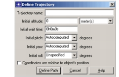
The Define Trajectory dialog box opens.
Figure 8: Define Trajectory Dialog Box
-
Enter a name for the trajectory.
-
Enter the altitude of the first trajectory position in the Initial altitude field and select the altitude units from the pull-down menu next to the altitude field.
-
Set the wait time for the first point in the Initial wait time field. A point’s wait time causes the mobile site to pause at that point for the specified interval before traversing the next segment.
You can use a standard time format (6:18:59) or an HMS format (6h18m59s). The HMS format does not require all three fields; 6h18m or 18m are valid. Decimals are permitted only in the right-most unit: 6:18:59.5 and 18.5m are valid entries, but 6.5:18:59 and 6h18.5m59s are not. If you enter a simple value like 23 or 59, the value is interpreted as seconds.
-
Set the pitch, yaw, and roll of the first point in the corresponding fields. See the descriptions of these fields in Table 4 for an explanation of the possible values.
-
Set the “Coordinates are relative to object’s position” checkbox to specify how the x, y, and altitude coordinates are interpreted.
If this checkbox is selected, the x and y coordinates are relative offsets from the mobile site’s initial position with respect to its parent subnet (as specified by the mobile site’s x position, y position, and altitude attributes).
If this checkbox is unselected, the coordinates are considered absolute values. The trajectory’s initial position coordinates replace the site’s x position, y position, and altitude attribute values.
-
Click the Define Path button.
The Trajectory Status dialog box opens and a thin diagonal line appears above the cursor in the Project Editor workspace.
Figure 9: Trajectory Status Dialog Box
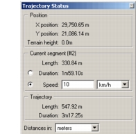
Note: The X position and Y position values will be labeled Latitude and Longitude, respectively, if those are the subnet units.
-
Left-click at the location for the first trajectory point. (For a relative trajectory, this point will be the mobile site.)
-
Specify a trajectory segment by clicking at the next point in the desired trajectory.
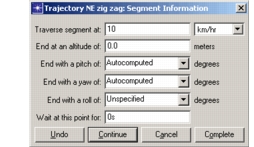
The Segment Information dialog box appears.
Figure 10: Segment Information Dialog Box
-
Enter the segment traverse time or speed (previous point to current point); ending values for altitude, pitch, yaw, and roll; and wait time for this point.
- You can express the traverse time as either a time or a velocity (km/hr, m/s, or mi/hr), depending on the setting in the Traverse segment pull-down menu. (You can also specify this in the Trajectory Status dialog box prior to drawing the segment.)
- When entering the altitude, use the same units (such as miles or kilometers) you used for the initial altitude.
- When specifying traversal time and wait time, follow the format constraints described in step 4.
To define more points, click Continue and specify the next point in the same way. When you have defined all the points in your trajectory, click Complete.
-
When you complete a trajectory definition, the trajectory is saved as an ASCII file with a .trj suffix in your primary models directory. If you started this procedure from a site’s pop-up menu, the trajectory is also assigned to that site.